Basic Guide How to Start Using TFT Graphic Library 2
Code advice:
To minimize RAM usage, many internal variables are reused across different library procedures. Care has been taken to prevent variable overwrites by selecting shared RAM locations only where procedures are not possible to be used together.
However, it is strongly recommended that you do not use the return value of one procedure directly as the input to another. Instead, always store the result in an independent intermediate variable.
Recommended approach:
myTempVariable = Procedure1()
Procedure2(myTempVariable)
Avoid:
Procedure2(Procedure1())
As TFT Graphic Library 2 has grown significantly and continues to expand, considerable effort is made to track variable usage and interactions in order to keep RAM consumption as low as possible. Nevertheless, due to the library’s size and complexity, there is always a possibility that some interactions may have been overlooked. Using intermediate variables provides an additional layer of safety and helps prevent unintended side effects.
TFT Screen:
The term "parallel port" here refers to configurations where a 16-bit port (e.g., PORTB) or two 8-bit ports (e.g., PORTB + PORTD) on the MCU connect directly to the TFT display’s parallel port.
-A 2x8-bit or 1x16-bit parallel data bus offers the fastest communication with the screen.
-For SPI TFT screens, a dedicated hardware SPI bus (one not shared with other peripherals) is ideal.
-If a hardware SPI isn’t available, a dedicated software SPI line is a good alternative.
-Shared software SPI lines offer the slowest communication speed.
Color inversion
Some TFT modules require color inversion to display colors correctly. This behavior is not dependent on the display driver IC, but on the specific TFT panel used in the module. By default, color inversion is disabled.
If you observe that Red, Green, Blue, Black, and White appear as Cyan, Magenta, Yellow, White, and Black, respectively, color inversion must be enabled. In this case, call TftInversionOn() after the TFT initialization sequence.
To disable color inversion, use the TftInversionOff() command.
RGB - BGR (Red, Green, Blue) order
To make matters more confusing, there is no standardized rule governing how display manufacturers connect the driver IC’s analog outputs to the TFT glass.
Internally, the driver IC does not work with “RGB565 pixels” as a packed format. Instead, pixel data is stored as separate Red, Green, and Blue components. The controller then drives three analog output channels: R_OUT, G_OUT, and B_OUT. The driver IC itself has no knowledge of which physical sub-pixel on the TFT glass corresponds to red, green, or blue.
That mapping is determined entirely by how the TFT glass is bonded to the controller. As a result, the TFT glass manufacturer decides the physical sub-pixel order, typically RGB or BGR.
For this reason, TFT Graphic Library 2 allows the default color order to be adjusted using the TftSetColorOrder() procedure, ensuring correct color reproduction regardless of the glass wiring.
SD Cards:
Many common TFT screens include an SD Card slot with a separate set of SPI lines. If your screen lacks an SD slot, one can be added to your design. The SD Card slot on TFT screens functions independently from the display’s graphic chip, using its own SPI pins.
Where possible, use a hardware SPI bus (a secondary SPI module) separate from the TFT screen. Speed is typically unaffected if the SD Card shares the SPI bus with other peripherals.
Software SPI is also an option. Using separate software SPI lines for the SD Card is ideal, but shared lines won’t significantly affect speed.
Note: If an SD Card is present but unused, keep its CS pin set high. Additionally, review the specific SPI bus speed considerations for 16-bit devices at the bottom of this page.
Memory:
Certain parallel TFT screens include a soldered FLASH memory chip or pins for adding one. However, this is rare on TFT screens using SPI. You can integrate a separate SPI memory chip in your PCB design as needed, just as with the SD Card slot.
Ideally, use a hardware SPI bus (a secondary SPI module) separate from the TFT screen. Shared SPI buses won’t impact speed for memory.
Software SPI is also possible, with best results on separate lines from the TFT, though sharing lines minimally impacts speed.
Note:
- Only SPI FLASH memory is currently supported, as larger EEPROMs (>1 MB) vary in architecture. SPI EEPROM support may be added later.
- If a memory IC is present but unused, keep its CS pin set high.
How to start with Positron8 and Positron16?
0. Support Les
Positron 8-bit and 16-bit PIC BASIC Compilers are excellent, user-friendly tools that generate fast and optimized code with several great IDE options. The Positron BASIC Community Forum is a welcoming community of enthusiasts and professionals who are ready to offer help.
1. Start with Library Defines
Directly after your Device and Declare sections, begin including library defines. Use TFT_Graphic_Lib.exe to generate the necessary ones. Include only all sections to your project even if a part of the library is not used. If a memory IC or SD Card shares an SPI bus with any other peripheral, remember to set their CS pins high, normally it is done in the library during boot time, but still good to be sure.
2. Include Font Files
After defining your settings, include all the font files needed for your project. Note that fonts are stored as full tables in MCU Flash memory, so each font will use additional program space.
You can include up to 256 SND (standard) fonts, but each SND font must have a unique font index (explained in the Library Description section).
BDF (Bitmap Distribution Format) fonts are also supported, with a maximum of 256 per project. Each BDF font must also have a unique font index. Instructions on creating BDF fonts from any TTF font are provided in the Bdf_To_Flash and FontForge guides.
Since SND and BDF fonts use separate procedures, an SND and a BDF font may share the same font index. The inclusion order for BDF and SND fonts does not matter.
3. Include TFT_Graphic_Lib.inc
Next, include the actual TFT_Graphic_Lib.inc file in your project. This file needs to be in the TftLib folder, and the folder structure should be preserved for the include files to function properly. Copy the entire TftLib folder (excluding the Tools subfolder) to your project’s main folder.
4. SD Card in RAW Mode
If you’re using an SD Card in RAW file mode (as explained in SdCardWriteRGB565), add any defines generated by SdCardWriteRGB565.exe.
Note: The order and structure of this section in Positron8 and Positron16 is crucial for successful integration.
Parallel Port Bus Speed Considerations:
For parallel bus TFT screens, speeds up to 100 MHz are generally supported. I've tested dsPIC at 170 MHz without any issues, as it takes at least 6 clock cycles for the PIC to latch 16-bit data to the TFT screen. With this setup, any 16-bit PIC running at standard clock speeds should handle parallel port screens without difficulty.
SPI Port Bus Speed Considerations for 8-bit MCUs:
Even the latest 8-bit PIC at 64 MHz is manageable for SPI transfers to TFT screens, SD Cards, and memory. Problems would only arise if a 1:1 clock source from Fosc is in use, in which case clean waveforms and PCB trace capacitance could impact performance more than clock speed limitations.
To configure the hardware SPI port:
Set CKE (SPI Clock Select bit) to 1: This sets transmission to occur on the transition from active to idle clock state.
Set SSPEN (Master Synchronous Serial Port Enable bit) to 1: This enables the serial port and configures the SCKx, SDOx, SDIx, and SSx as serial port pins.
|
SSP1STAT = 0x40 SSP1CON1 = 0x20 'SPI enable 'or SSP2STAT = 0x40 SSP2CON1 = 0x20 'SPI enable |
Starting with Lower Clock Speeds for Testing: When first testing with SPI or parallel ports, it's best to start with a lower clock speed, such as Fosc/8, to verify that the basic functionality works (e.g., printing text). Once you've confirmed the basic operation, you can gradually increase the clock speed and test for stability.
Baud/Speed Considerations for Hardware SPI Bus in 16-bit MCUs:
For 16-bit MCUs, such as some dsPICs, that can run at speeds up to 160 MHz, there are some important considerations when using the hardware SPI port:
SD Card Performance:
SD Cards generally support SPI clock speeds from 25-35 MHz. However, I've discovered that this is primarily limited by the delay between each byte shifted in. By allowing enough delay between bytes, SPI clocks up to 70-80 MHz can still work with no issues.
In 8-bit mode, two bytes can be sent with an 80 MHz SPI clock since the delay between the bytes (due to the clearing and loading of the SPI register) allows the SD Card to process them properly. However, in 16-bit mode, the SD Card controller (which works with 8-bit data) won’t have enough time to process the byte properly if you send two bytes as a single 16-bit word, even at a 40 MHz clock.
Important Note: SD cards have different read and write speed limitations. While an SD card may allow reading at an SPI clock speed of 70 MHz, it doesn’t mean it can handle writing at that same speed. In my experiments, the maximum stable write speed was around 35 MHz SPI clock. Therefore, if your program requires both reading from and writing to an SD card, you will need to adjust the SPI clock speed dynamically to accommodate these differing requirements.
Memory ICs:
Memory ICs can typically handle clock speeds of 60-70 MHz without any issues, so they're less sensitive to high clock speeds compared to SD Cards.
TFT Screens with SPI Port:
TFT Screens with SPI ports usually accept clock rates of 60-70 MHz, but speeds up to 80 MHz have not caused issues in my tests. Also, 16-bit MCUs generally produce much cleaner waveforms than 8-bit MCUs, which helps with stability at higher clock speeds.
SPI Clock Prescaler Considerations:
On 16-bit MCUs, the SPI clock prescaler can be set to 1:1 (Fosc clock), but this is generally considered an invalid setting if the MCU is running at a high clock speed (e.g., 150 MHz). Instead, you would need to set a prescaler of 1:2 or 1:4. For lower MCU clock speeds (e.g., 60 MHz), it might be worth experimenting with a 1:1 prescaler for the SPI clock, although the datasheet may suggest it's not valid.
To configure the hardware SPI port on a 16-bit MCU, use the following settings:
-Set SMP: SPIx Data Input Sample Phase bit to 1 = Input data is sampled at the end of the data output time.
-Set CKE: SPIx Clock Edge Select bit to 1 = Serial output data changes on the transition from the Active Clock state to the Idle Clock state.
-Set MSTEN: Master Mode Enable bit to 1 = Enables Master mode operation.
-Set SPIEN: SPIx Enable bit to 1 = Enables the SPI module and configures the SCKx, SDOx, SDIx, and SSx as serial port pins.
By following these guidelines, you can ensure proper communication with peripherals and optimize the SPI bus speed for both SD Cards and TFT screens.
|
SPI1CON1 = 0x033B 'SPRE[2:0] 2:1 / PPRE[1:0] 1:1 SPI1STAT = 0x8000 'SPI enable 'or SPI2CON1 = 0x033B 'SPRE[2:0] 2:1 / PPRE[1:0] 1:1 SPI2STAT = 0x8000 'SPI enable |
Starting with Lower Clock Speeds for Testing: Start with lower clock speeds initially to confirm basic functionality, such as printing text, works correctly. Once that is verified, gradually increase the SPI clock speed and continue testing for stability at each step. This approach helps ensure reliable communication and allows you to identify any issues that might arise as the clock speed increases.
TFT Screen Data Reading:
TFT screens have different speed limitations for reading and writing. While a TFT screen may support writing at a SPI clock speed of 70 MHz, it typically cannot handle reading at the same speed. In most cases, you will need to lower the SPI clock speed for reading data from the TFT screen and then restore the higher clock speed for writing.
In general, the SPI clock speed cannot be changed on-the-fly. To adjust the clock speed, you must disable the SPI module, modify the clock settings, and then re-enable the module. Below is an example of how this process is implemented on a 16-bit MCU.
When using the hardware SPI_1 or SPI_2 interfaces, reading data from the TFT module typically requires a lower SPI clock speed (6-8 MHz or less) than writing data to it. Due to the wide variety of 8-bit and 16-bit PIC MCUs, the SPI register layout and clock-divider settings differ between devices and cannot be handled in a fully universal way.
For this reason, the library requires two user-defined inline commands to explicitly change the SPI clock speed:
- one for slower SPI operation during read cycles
- one for restoring the normal SPI speed for write operations.
These commands are defined as:
$define TFT_COM_Slow ' Lower SPI clock speed (used before reading from TFT)
$define TFT_COM_Fast ' Restore normal SPI clock speed (used for writing to TFT)
Example (16b PIC SPI2 configuration):
|
$define TFT_COM_Slow SPI2STAT = 0X0000 : SPI2CON1 = 0X0323 : SPI2BUF = 0 : SPI2STAT = 0X8000 $define TFT_COM_Fast SPI2STAT = 0X0000 : SPI2CON1 = 0X033B : SPI2BUF = 0 : SPI2STAT = 0X8000 |
Whenever the MCU needs to read from the TFT module, the library first executes TFT_COM_Slow to reduce the SPI clock. After the read operation completes, it executes TFT_COM_Fast to return to the normal write speed.
Internally, the sequence effectively looks like this:
' Switch to slow SPI clock
SPI2STAT = 0x0000 : SPI2CON1 = 0x0323 : SPI2BUF = 0 : SPI2STAT = 0x8000
' Read data from the TFT module'
' ...
' Restore normal SPI clock
SPI2STAT = 0x0000 : SPI2CON1 = 0x033B : SPI2BUF = 0 : SPI2STAT = 0x8000
' Continue program execution
This approach allows the library to remain MCU-independent while still ensuring reliable TFT read operations across different PIC devices.
TFT screens with parallel ports that I’ve tested work reliably at high dsPIC clock speeds. Since the data transfer is software-based, there is sufficient delay for the data to be latched even at a 160 MHz dsPIC clock.
Note: Some displays support TFT GRAM pixel readback only via a single data line. Although a MISO pin may be present, it is often not internally connected. In such cases, GRAM readback must be performed in single-line (bidirectional) mode using the MOSI pin. Configure the MISO pin to the same physical pin as MOSI.
Pixel Verification for Screen Boundaries:
This setting determines whether pixel verification is applied when drawing shapes, symbols, or fonts that extend beyond the screen boundaries.
When enabled:
Any pixels falling outside the screen width and/or height will be ignored.
Shapes or symbols extending beyond the screen's maximum width and height will be partially drawn within the screen limits.
If a shape or symbol starts below the screen's origin (0-point), it will not be drawn at all.
However, enabling this feature requires additional computational resources, which may affect performance.
When disabled:
No boundary verification is performed, resulting in faster execution. However, this can lead to unpredictable behavior if shapes or symbols extend beyond the screen's borders.
Note: Enabling "Pixel Verification" is not foolproof and may not handle all edge cases. It is recommended that user programs perform additional verification of shape and figure coordinates to ensure proper operation.
Screen-to-GRAM Misalignment:
Not all TFT screens are perfectly aligned with the graphic RAM in their controllers. This alignment varies by manufacturer, meaning the actual starting pixel (X=0, Y=0) on the TFT screen may not correspond to the 0th row and 0th column in the controller's graphic RAM.
For instance, consider a 160x80 pixel screen that is misaligned with the graphic RAM. To draw a rectangle spanning the entire screen (from pixel 0,0 to pixel 159,79), you cannot directly use these values in the controller because of the offset. If the offset is 1 pixel in the width (X) direction and 26 pixels in the height (Y) direction, the actual coordinates to be written to the graphic RAM would be (1,26) for the starting point and (160,105) for the ending point.
Manually adjusting for such offsets in user code can be error-prone and cumbersome. To simplify this, you can define the offsets using TftWidthOffset and TftHeightOffset. The library will then automatically account for these offsets, allowing the user to work with intuitive screen coordinates without concern for the underlying misalignment.
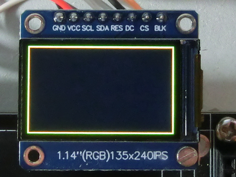
An easy way to determine the screen misalignment offset is as follows. Assume a TFT screen with a resolution of 240x135 pixels:
- Reset the screen to a black color, set TftWidthOffset and TftHeightOffset to 0 and draw two empty rectangles using different colors.
For first rectangle set corner 1 to coordinates (1,1) and corner 3 to (ScreenWidth - 2, ScreenHeight - 2) -this should result in a rectangle that is 1 pixel away from each edge of the screen.
For second rectangle set corner 1 to coordinates (0,0) and corner 3 to (ScreenWidth - 1, ScreenHeight - 1) -this should result in a rectangle that is 0 pixel away from each edge of the screen.
|
$define TftWidthOffset 0 $define TftHeightOffset 0 ... TftRectangleENTC(1,1,238,133,RED) TftRectangleENTC(0,0,239,134,GREEN) |
- Observe the screen to check if the rectangles appear as 1 pixel and 0 pixel away from each edge.
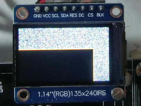
- Adjust the TftWidthOffset and TftHeightOffset values based on the observed offset.
|
$define TftWidthOffset 30 $define TftHeightOffset 40 |
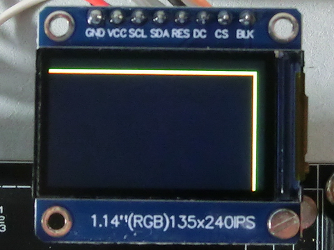
- Repeat the process until the rectangles appears correctly positioned as 1 pixel and 0 pixel away from each edge.
|
$define TftWidthOffset 40 $define TftHeightOffset 52 |
Created with the Personal Edition of HelpNDoc: Maximize Your CHM Help File Capabilities with HelpNDoc