SPI
… visits


SPI (Serial Peripheral Interface)
There are two SPI interface options available for connecting an EPD module: software SPI and hardware SPI.
Software SPI uses bit-banging implemented in software, while hardware SPI uses the microcontroller's dedicated SPI peripheral.
Although some modern PIC microcontrollers provide multiple SPI modules, TFT & EPD Graphic Library 2 uses only SPI1 or SPI2 when operating in hardware SPI mode.
Unlike a TFT write, an EPD refresh command doesn't complete when the MCU finishes sending it — the controller continues driving the waveform internally, on its own clock, for as long as the update takes.
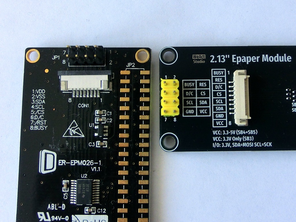
Almost all EPD controllers expose a BUSY pin specifically so the host can tell when this internal process has actually finished, and a new command must not be issued while the controller is still mid-refresh, or the in-progress update can be corrupted.
(This library handles BUSY polling automatically — see "Communicating With the Controller" — but the pin is still part of the required wiring.)
Most controllers have no RAM readback capability at all — and even where the silicon technically supports it, it's rarely exposed or reliable on inexpensive modules — so the SDA line is practically used for writes only, not for reading back image/RAM data (or registers because there is no practical use of that).
|
SPI Interface Signal Lines:
Additional Power and Control Lines (Non-SPI):
NotesThere is no universal standard pinout, though manufacturers tend to be fairly consistent among themselves. |
|
Created with the Personal Edition of HelpNDoc: Maximize Your Reach: Convert Your Word Document to an ePub or Kindle eBook