Use only SD Card Library
… visits


HOW TO SET-UP THE LIBRARY FOR SD CARD CODE ONLY
This guide explains how to use only the SD card functionality from the TFT Library. The PIC TFT Library is primarily designed for TFT displays, with SD card support included as one of its modules.
You can download the full library from the link at the top of the homepage.
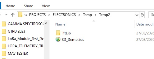
Note: You may remove font files to reduce size, but keep the font folders themselves.
The setup tool expects these folders to exist and may warn if they are missing (although it will still function).
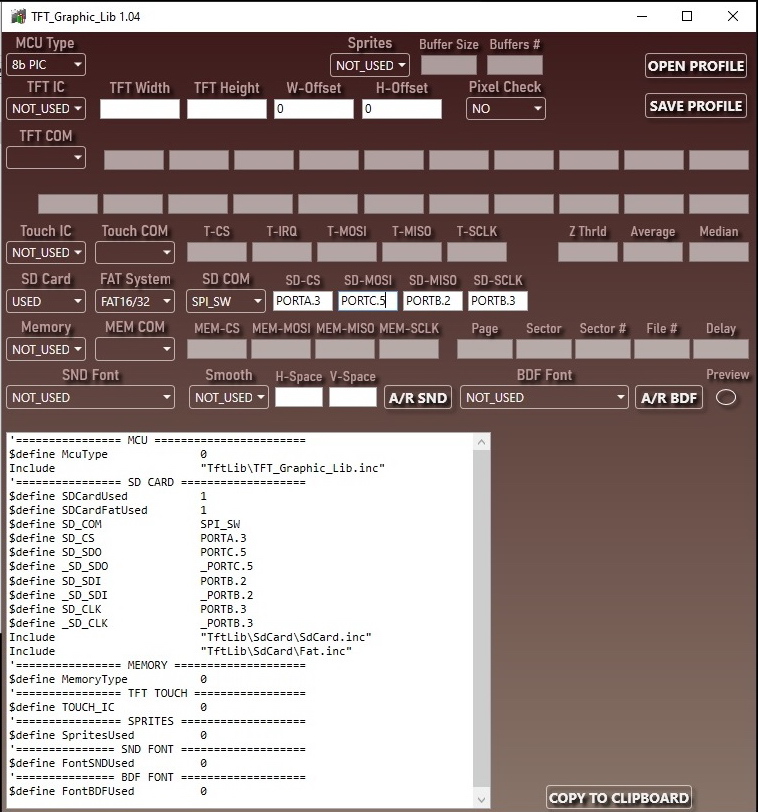
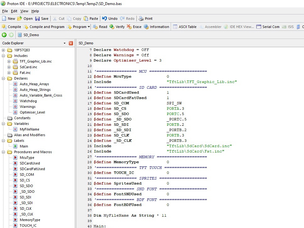
Once configured, the SD card functions can be used in the same way as the original FileSys24 library.
This version also supports 8-bit MCUs. For detailed command descriptions and usage examples, refer to the SD Card FAT16/32 section in the library documentation.
An example project file is included to help you get started:
|
Device = 18F57Q83 Declare Xtal = 64 Declare Auto_Heap_Arrays = On Declare Auto_Heap_Strings = On Declare Auto_Variable_Bank_Cross = On Declare Watchdog = OFF Declare Warnings = Off Declare Optimiser_Level = 3 '================ MCU ======================= $define McuType 0 Include "TftLib\TFT_Graphic_Lib.inc" '================ SD CARD =================== $define SDCardUsed 1 $define SDCardFatUsed 1 $define SD_COM SPI_SW $define SD_CS PORTA.3 $define SD_SDO PORTC.5 $define _SD_SDO _PORTC.5 $define SD_SDI PORTB.2 $define _SD_SDI _PORTB.2 $define SD_CLK PORTB.3 $define _SD_CLK _PORTB.3 Include "TftLib\SdCard\SdCard.inc" Include "TftLib\SdCard\Fat.inc" '================ MEMORY ==================== $define MemoryType 0 '================ TFT TOUCH ================= $define TOUCH_IC 0 '================ SPRITES =================== $define SpritesUsed 0 '=============== SND FONT =================== $define FontSNDUsed 0 '=============== BDF FONT =================== $define FontBDFUsed 0 Dim MyFileName As String * 11 Main: Clear SetCrystal() SetPins() File_Init() End 'Set Fosc Proc SetCrystal() Clear OSCCON1 = %01100000 OSCEN.6 = 1 OSCFRQ = %00001000 DelayMS 100 EndProc Proc SetPins() 'Set all digital ANSELA = 0 ANSELB = 0 ANSELC = 0 ANSELD = 0 ANSELE = 0 ANSELF = 0 EndProc '**** Added by Fuse Configurator **** Config_Start FEXTOSC = OFF ;Oscillator not enable RSTOSC = HFINTOSC_64MHZ ;HFINTOSC with HFFRQ = 64 MHz and CDIV = 1: CLKOUTEN = OFF ;CLKOUT function is disable PR1WAY = OFF ;PRLOCKED bit can be set and cleared repeatedl CSWEN = On ;Writing to NOSC and NDIV is allowe JTAGEN = OFF ;Disable JTAG Boundary Scan FCMEN = On ;Fail-Safe Clock Monitor enable FCMENP = OFF ;FSCM timer will not set FSCMP bit or OSFIF interrupt on Primary XTAL failur FCMENS = OFF ;FSCM timer will not set FSCMS bit or OSFIF interrupt on Secondary XTAL failur MCLRE = EXTMCLR ;If LVP = 0, MCLR pin is MCLR; If LVP = 1, RE3 pin function is MCLR PWRTS = PWRT_OFF ;PWRT is disable MVECEN = OFF ;Interrupt contoller does not use vector table to prioritze interrupt IVT1WAY = OFF ;IVTLOCKED bit can be cleared and set repeatedl LPBOREN = OFF ;Low-Power BOR disable BOREN = SBORDIS ;Brown-out Reset enabled , SBOREN bit is ignore BORV = VBOR_1P9 ;Brown-out Reset Voltage (VBOR) set to 1.9 ZCD = OFF ;ZCD module is disabled. ZCD can be enabled by setting the ZCDSEN bit of ZCDCO PPS1WAY = OFF ;PPSLOCKED bit can be set and cleared repeatedly (subject to the unlock sequence STVREN = On ;Stack full/underflow will cause Rese LVP = On ;LV programming XINST = OFF ;Extended Instruction Set and Indexed Addressing Mode disable WDTCPS = WDTCPS_31 ;Divider ratio 1:65536; software control of WDTP WDTE = OFF ;WDT Disabled; SWDTEN is ignore WDTCWS = WDTCWS_7 ;window always open (100%); software control; keyed access not require WDTCCS = SC ;Software Contro BBSIZE = BBSIZE_512 ;Boot Block size is 512 word BBEN = OFF ;Boot block disable SAFEN = On ;SAF enable WRTB = OFF ;Boot Block not Write protecte WRTC = OFF ;Configuration registers not Write protecte WRTD = OFF ;Data EEPROM not Write protecte WRTSAF = OFF ;SAF not Write Protecte WRTAPP = OFF ;Application Block not write protecte BOOTPINSEL = RC5 ;CRC on boot output pin is RC BPEN = OFF ;CRC on boot output pin disable ODCON = OFF ;Pin drives both high-going and low-going signal Cp = OFF ;PFM and Data EEPROM code protection disable BOOTSCEN = OFF ;CRC on boot will not include the boot area of program memory in its calculatio BOOTCOE = Continue ;CRC on boot will allow device to continue code execution regardless of error detection in boot area APPSCEN = OFF ;CRC on boot will not include the application area of program memory in its calculatio SAFSCEN = OFF ;CRC on boot will not include the SAF area of program memory in its calculatio DATASCEN = OFF ;CRC on boot will not include data EEPROM in its calculatio CFGSCEN = OFF ;CRC on boot will not include the configuration fuses in its calculatio COE = HALT ;CRC on boot will stop device if error is detected in non-boot area BOOTPOR = OFF ;CRC on boot will not ru BCRCPOLT = HFF ;BCRCPOL is 0xF Config_End '**** End of Fuse Configurator Settings **** |
Created with the Personal Edition of HelpNDoc: Save time and frustration with HelpNDoc's WinHelp HLP to CHM conversion feature