Oscillator Frequency Declare.
Declare Xtal = Frequency (in MHz).
Inform the compiler what frequency oscillator is being used. For example:
Declare Xtal = 7.37or
Declare Xtal = 80Some commands are very dependant on the oscillator frequency, Rsin, Rsout, DelayMs, and DelayUs being just a few. In order for the compiler to adjust the correct timing for these commands, it must know what frequency crystal is being used.
Note
The Xtal declare will not alter any fuse settings or SFRs (Special Function Registers) relating to the oscillator setup. There is no default value if the Declare is not issued in a program, and it should be considered as a mandatory addition to the code.
PIC24® and dsPIC33® devices have a multitude of oscillator options, therefore, they cannot all be detailed in this manual. However, shown below are some examples that illustrate methods of using an external crystal and the internal oscillator, both with and without the PLL multiplier.
Example 1
' PIC24F external 8MHz crystal operating at 32MHz using PLL
'
  Device = 24FJ64GA002
  Declare Xtal = 32

  CLKDIV = 0                   ' CPU peripheral clock ratio set to 1:1
  OSCCON.Byte1 = %00010000  ' Enable 4 x PLL '
'
' Flash an LED connected to PORTA.0
'
  Do
     PinHigh PORTA.0
     DelayMs 500
     PinLow PORTA.0
     DelayMs 500
  Loop
'
' For external oscillator with PLL
'
  Config Config1 = JTAGEN_OFF, GCP_OFF, GWRP_OFF, BKBUG_OFF,_
                      COE_OFF, ICS_PGx1, FWDTEN_OFF, WINDIS_OFF,_
                      FWPSA_PR128, WDTPOST_PS256
  Config Config2 = IOL1WAY_OFF, IESO_OFF, FNOSC_PRIPLL,_
                      FCKSM_CSDCMD,OSCIOFNC_OFF, POSCMOD_HS
Example 2
' PIC24F internal 8MHz oscillator operating at 32MHz using PLL
'
  Device = 24FJ64GA002
  Declare Xtal = 32

  CLKDIV = 0                   ' CPU peripheral clock ratio set to 1:1
  OSCCON.Byte1 = %00010000  ' Enable 4 x PLL
'
' Flash an LED connected to PORTA.0
'
  Do
     PinHigh PORTA.0
     DelayMs 500
     PinLow PORTA.0
     DelayMs 500
  Loop
'
' For internal 8MHz oscillator with PLL
' OSC pins operate as general purpose I/O
'
  Config Config1 = JTAGEN_OFF, GCP_OFF, BKBUG_OFF,_
                      COE_OFF, ICS_PGx1, FWDTEN_OFF, WINDIS_OFF,_
                      FWPSA_PR128, WDTPOST_PS256
  Config Config2 = IOL1WAY_OFF, IESO_OFF, FNOSC_PRIPLL,_
                      FCKSM_CSECME, OSCIOFNC_OFF, POSCMOD_NONE
Example 3
' PIC24H internal 7.37MHz oscillator operating at 79.23MHz using PLL
'
    Device = 24HJ128GP502
    Declare Xtal = 79.23
'-------------------------------------------------------------------
Main:
' Configure the Oscillator to operate the device at 79.23MHz
' Fosc = (7.37 * 43) / (2 * 2) = 79.23MHz (40 MIPS)
'
  PLL_Setup(43, 2, 2, $0300)
'
' Flash an LED connected to PORTA.0
'
  Do
     PinHigh PORTA.0
     DelayMs 500
     PinLow PORTA.0
     DelayMs 500
  Loop
'
' For internal 7.37MHz oscillator with PLL
' OSC pins operate as general purpose I/O
'
    Config FBS = BWRP_WRPROTECT_OFF
    Config FSS = SWRP_WRPROTECT_OFF
    Config FGS = GWRP_OFF
    Config FOSCSEL = FNOSC_FRCPLL, IESO_OFF
    Config FOSC = POSCMD_NONE, OSCIOFNC_OFF, IOL1WAY_OFF, FCKSM_CSECME
    Config FWDT = WDTPOST_PS256, WINDIS_OFF, FWDTEN_OFF
    Config FPOR = FPWRT_PWR128, ALTI2C_OFF
    Config FICD = ICS_PGD1, JTAGEN_OFF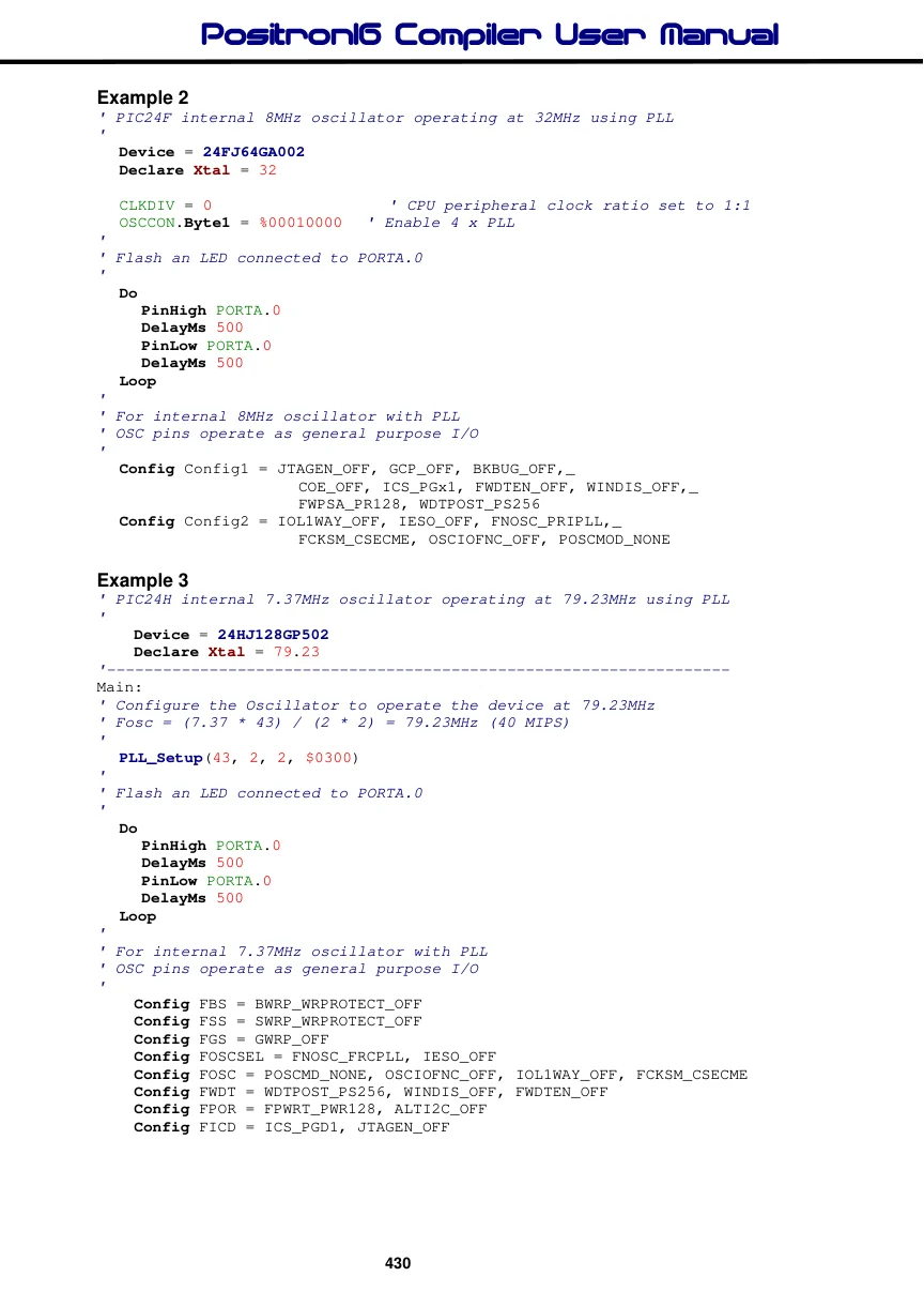
Example 4
' PIC24E internal 7.37MHz oscillator operating at 140.03MHz using PLL
'
    Device = 24EP128MC202
    Declare Xtal = 140.03
'-------------------------------------------------------------------
Main:
' Configure the Oscillator to operate the device at 140.03MHz (70 MIPS)
' Fosc = (7.37 * 76) / (2 * 2) = 140.03MHz
'
  PLL_Setup(76, 2, 2, $0300)
'
' Flash an LED connected to PORTA.0
'
  Do
     PinHigh PORTA.0
     DelayMs 500
     PinLow PORTA.0
     DelayMs 500
  Loop
'
' For internal 7.37MHz oscillator with PLL
' OSC pins operate as general purpose I/O
'
  Config FGS = GWRP_OFF
  Config FOSCSEL = FNOSC_FRCPLL, IESO_OFF, PWMLOCK_OFF
  Config FOSC = POSCMD_NONE, OSCIOFNC_ON, IOL1WAY_OFF, FCKSM_CSECME
  Config FWDT = WDTPOST_PS256, WINDIS_OFF, PLLKEN_ON, FWDTEN_OFF
  Config FPOR = ALTI2C1_ON, ALTI2C2_OFF
  Config FICD = ICS_PGD1, JTAGEN_OFF
Example 5
' ds33CK128MP202 internal oscillator operating at 190.0MHz
'
    Device = 33CK128MP202
    Declare Xtal = 190.00
'-------------------------------------------------------------------
Main:
  Osc_190MHz()          ' Setup the device to operate at 190MHz
'
' Flash an LED connected to PORTA.0
'
  Do
     PinHigh PORTA.0
     DelayMs 500
     PinLow PORTA.0
     DelayMs 500
  Loop

'-------------------------------------------------------------------
' Setup the device to operate at 190MHz with its internal oscillator
' Input     : None
' Output    : None
' Notes     : Waits for the oscillator to become stable
'
Proc Osc_190MHz()
  CLKDIV = $3001  ' FRCDIV FRC/1, PLLPRE 1, DOZE 1:8, DOZEN disabled, ROI disabled
  PLLFBD = 90
  OSCTUN = $00
  PLLDIV = $21              ' POST1DIV 1:2, VCODIV FVCO/4, POST2DIV 1:1
  ACLKCON1 = $0101          ' APLLEN disabled, FRCSEL FRC, APLLPRE 1:1
  APLLFBD1 = $C8
  APLLDIV1 = $42            ' APOST1DIV 1:4, APOST2DIV 1:2, AVCODIV FVCO/4

  Write_OSCCONH($01)
  Write_OSCCONL($01)

  While OSCCONbits_OSWEN <> 0 : Wend  ' Wait for the clock switch to occur
EndProc

'-------------------------------------------------------------------
' Set the fuses for internal oscillator
' OSC pins operate as general purpose I/O
'
  Config FSEC    = BWRP_OFF, BSS_DISABLED, BSEN_OFF, GWRP_OFF, GSS_DISABLED,_
                    CWRP_OFF, CSS_DISABLED, AIVTDIS_OFF
  Config FOSCSEL = FNOSC_FRC, IESO_OFF
  Config FOSC    = POSCMD_NONE, OSCIOFNC_ON, FCKSM_CSECMD, PLLKEN_ON, XTCFG_G0,_
                    XTBST_ENABLE
  Config FWDT    = SWDTPS_PS2147483648, RCLKSEL_LPRC
  Config FPOR    = BISTDIS_DISABLED
  Config FICD    = ICS_PGD1, JTAGEN_OFF, NOBTSWP_DISABLED
  Config FDMT    = DMTDIS_OFF
  Config FDEVOPT = ALTI2C1_OFF,ALTI2C2_OFF,ALTI2C3_OFF, SMBEN_STANDARD, SPI2PIN_PPS
  Config FALTREG = CTXT1_OFF, CTXT2_OFF, CTXT3_OFF, CTXT4_OFF
  Config FBOOT   = BTMODE_SINGLE
Note.
The PLL_Setup helper macro can be found within the device’s “.def” file. It is required because the dsPIC33®, PIC24E® and PIC24H® devices need an unlock sequence before writing to the OSCCON SFR, unlike the PIC24F® devices, that can write directly to the OSCCON SFR.
