Shout
Syntax
Shout Data_Pin, Clk_Pin, Mode, [OutputData {\Bits} {,OutputData {\Bits}..} ]
Overview
Shift data out to a synchronous serial device. i.e. SPI.
Parameters
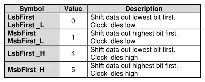
Data_Pin is a Port.Pin value that specifies the I/O pin that will be connected to the synchronous serial device's data input. This pin will be set to output mode. Clk_Pin is a Port.Pin value that specifies the I/O pin that will be connected to the synchronous serial device's clock input. This pin will be set to output mode. Mode is a constant that tells Shout the order in which data bits are to be arranged. Below are the symbols, values, and their meanings: -
Text in this figure or table
| Symbol | Value | Description |
| LsbFirst | Shift data out lowest bit first. |
0
| LsbFirst _L | Clock idles low |
| MsbFirst | Shift data out highest bit first. |
1
MsbFirst_L Clock idles low
Shift data out lowest bit first.
LsbFirst _H 4
Clock idles high Shift data out highest bit first.
MsbFirst_H 5
Clock idles high
OutputData is a variable, constant, or expression containing the data to be sent. Bits is an optional constant specifying how many bits are to be output by Shout. If no Bits entry is given, Shout defaults to 8 bits.
Notes
Shin and Shout provide a method of acquiring data from synchronous serial devices. Data bits may be valid after the rising or falling edge of the clock line. This kind of serial protocol is commonly used by controller peripherals like ADCs, DACs, clocks, memory devices, etc.
At their heart, synchronous-serial devices are essentially shift-registers; trains of flip flops that receive data bits in a bucket brigade fashion from a single data input pin. Another bit is input each time the appropriate edge (rising or falling, depending on the device) appears on the clock line.
The Shout instruction first causes the clock pin to output low and the data pin to switch to output mode. Then, Shout sets the data pin to the next bit state to be output and generates a clock pulse. Shout continues to generate clock pulses and places the next data bit on the data pin for as many data bits as are required for transmission.
Making Shout work with a particular device is a matter of matching the mode and number of bits to that device's protocol. Most manufacturers use a timing diagram to illustrate the relationship of clock and data. One of the most important items to look for is which bit of the data should be transmitted first; most significant bit (MSB) or least significant bit (LSB).

Example
Shout DTA_Pin, CLK_Pin, MsbFirst, [250]In the above example, the Shout command will write to I/O pin DTA (the Dpin) and will generate a clock signal on I/O CLK (the Cpin). The Shout command will generate eight clock pulses while writing each bit (of the 8-bit value 250) onto the data pin (Dpin). In this case, it will start with the most significant bit first as indicated by the Mode value of MsbFirst.
By default, Shout transmits eight bits, but you can set it to shift any number of bits from 1 to 16 with the Bits argument. For example: -
Shout DTA_Pin, CLK_Pin, MsbFirst, [250\4]Will only output the lowest 4 bits (binary 0000 in this case). Some devices require more than 16 bits. To solve this, you can use a single Shout command with multiple values. Each value can be assigned a particular number of bits with the Bits argument. As in: -
Shout DTA_Pin, CLK_Pin, MsbFirst, [250\4, 1045\16]The above code will first shift out four bits of the number 250 (binary 1111) and then 16 bits of the number 1045 (binary 0000010000010101). The two values together make up a 20 bit value.
See also : Shin.