Xout
Syntax
Xout DataPin, ZeroPin, [HouseCode\KeyCode {\Repeat} {, ...}]
Overview
Transmit a HouseCode followed by a KeyCode in X-10 format.
Parameters
DataPin is a constant (0 - 15), Port.Bit, or variable, that transmits the data to an X-10 interface. This pin is automatically made an output. ZeroPin is a constant (0 - 15), Port.Bit, or variable, that is used to synchronise to a zero-cross event. This pin is automatically made an input to received the zero crossing timing, and should also be pulled up to 5 Volts with a 4.7KΩ resistor. HouseCode is a number between 0 and 15 that corresponds to the House Code set on the X- 10 module A through P. The proper HouseCode must be sent as part of each command. KeyCode can be either the number of a specific X-10 module, or the function that is to be performed by a module. In normal use, a command is first sent specifying the X-10 module number, followed by a command specifying the function required. Some functions operate on all modules at once so the module number is unnecessary. KeyCode numbers 0-15 correspond to module numbers 1-16. Repeat is an optional parameter, and if it is not included, then a repeat of 2 times (the minimum) is assumed. Repeat is normally reserved for use with the X-10 Bright and Dim commands.
Example
  Dim House as Byte
  Dim Unit as Byte
' Create some aliases of the keycodes
  Symbol UnitOn = 0b10010      ' Turn module on
  Symbol UnitOff = 0b11010      ' Turn module off
  Symbol UnitsOff = 0b11100   ' Turn all modules off
  Symbol LightsOn = 0b10100   ' Turn all light modules on
  Symbol LightsOff = 0b10000  ' Turn all light modules off
  Symbol Bright = 0b10110      ' Brighten light module
  Symbol DimIt = 0b11110        ' Dim light module
' Create aliases for the pins used
  Symbol DataPin = PORTA.1
  Symbol ZeroC = PORTA.0
  House = 0                      ' Set house to 0 (A)
  Unit = 8                      ' Set unit to 8 (9)
' Turn on unit 8 in house 0
  Xout DataPin ,ZeroC,[House \ Unit,House \ UnitOn ]
' Turn off all the lights in house 0
  Xout DataPin ,ZeroC,[House \ LightsOff ]
  Xout DataPin ,ZeroC,[House \ 0]
' Blink light 0 on and off every 10 seconds
MyLoop:
  Xout DataPin ,ZeroC,[House \ UnitOn ]
  DelayMs 10000               ' Wait 10 seconds
  Xout DataPin ,ZeroC,[House \ UnitOff ]
  DelayMs 10000               ' Wait 10 seconds
  GoTo MyLoop
Xout and Xin Declares
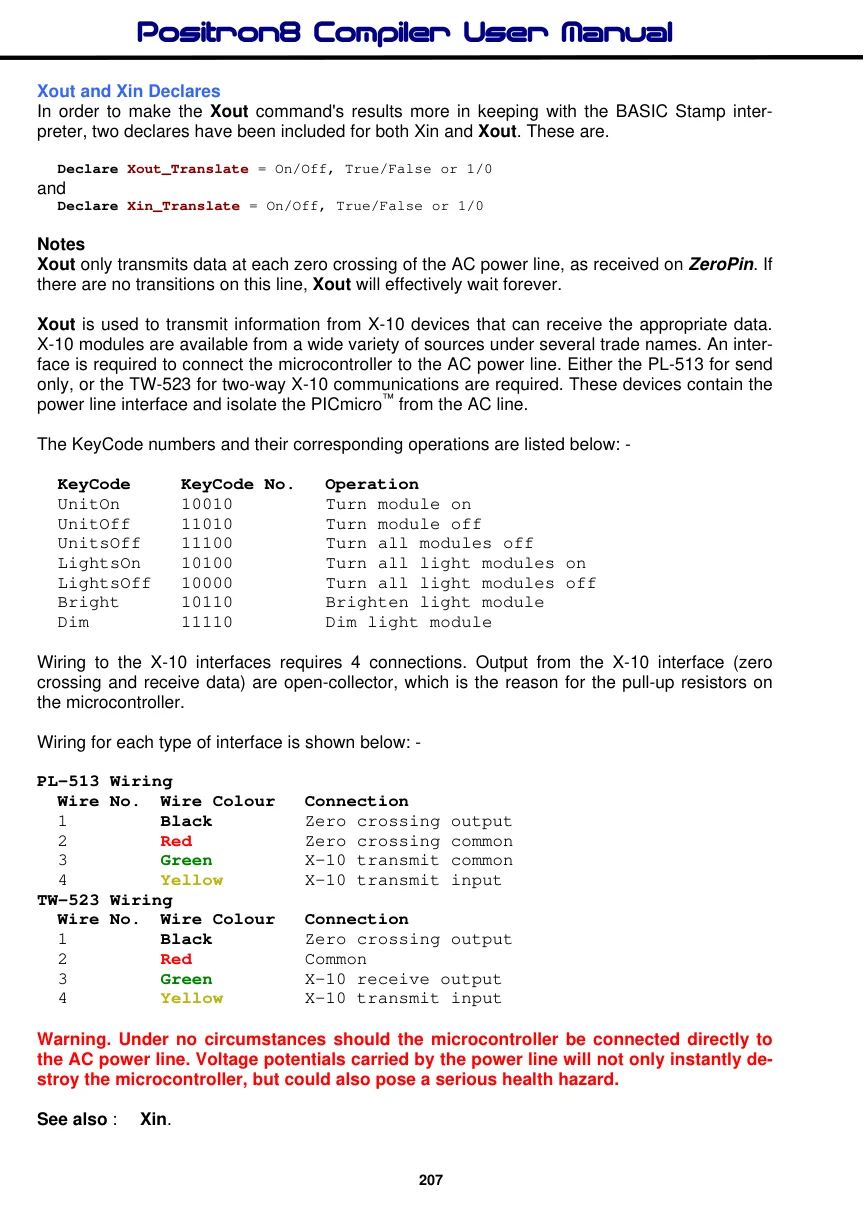
In order to make the Xout command's results more in keeping with the BASIC Stamp interpreter, two declares have been included for both Xin and Xout. These are.
Declare Xout_Translate = On/Off, True/False or 1/0and
Declare Xin_Translate = On/Off, True/False or 1/0Notes
Xout only transmits data at each zero crossing of the AC power line, as received on ZeroPin. If there are no transitions on this line, Xout will effectively wait forever.
Xout is used to transmit information from X-10 devices that can receive the appropriate data. X-10 modules are available from a wide variety of sources under several trade names. An interface is required to connect the microcontroller to the AC power line. Either the PL-513 for send only, or the TW-523 for two-way X-10 communications are required. These devices contain the power line interface and isolate the PICmicro™ from the AC line.
The KeyCode numbers and their corresponding operations are listed below: -
 KeyCode   KeyCode No.  Operation
 UnitOn   10010      Turn module on
 UnitOff   11010      Turn module off
 UnitsOff  11100      Turn all modules off
 LightsOn  10100      Turn all light modules on
 LightsOff  10000      Turn all light modules off
 Bright   10110      Brighten light module
 Dim     11110      Dim light module
Wiring to the X-10 interfaces requires 4 connections. Output from the X-10 interface (zero crossing and receive data) are open-collector, which is the reason for the pull-up resistors on the microcontroller.
Wiring for each type of interface is shown below: -
PL-513 Wiring
 Wire No. Wire Colour  Connection
 1      Black     Zero crossing output
 2      Red      Zero crossing common
 3      Green     X-10 transmit common
 4      Yellow    X-10 transmit input
TW-523 Wiring
 Wire No. Wire Colour  Connection
 1      Black     Zero crossing output
 2      Red      Common
 3      Green     X-10 receive output
 4      Yellow    X-10 transmit input
Warning. Under no circumstances should the microcontroller be connected directly to the AC power line. Voltage potentials carried by the power line will not only instantly destroy the microcontroller, but could also pose a serious health hazard.
See also : Xin.