EPD Graphic Library Set-up Tool
(Current version 1.00)
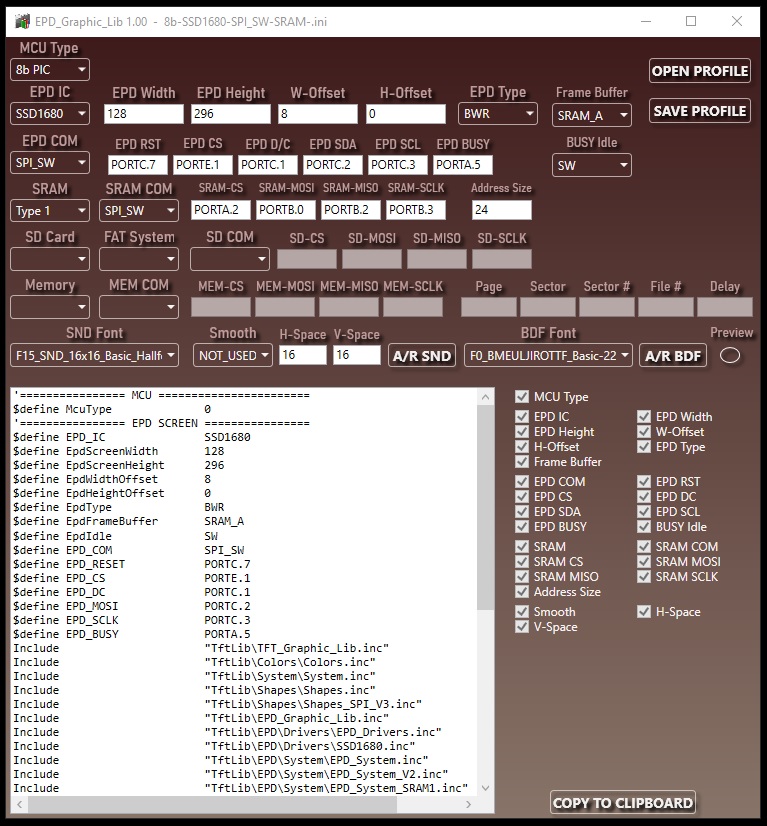
EPD_Graphic_Lib.exe is the main tool used to properly configure TFT & EPD Graphic Library 2 for EPD displays.
It automatically generates all the necessary include files required by your program. Due to the increasing complexity of the library, this tool is now mandatory, as it ensures that only the required optimized files are included and always in the correct order, based on your selected settings.
In addition, the tool provides new features such as saving and loading configuration profiles, and previewing fonts (BDF or Standard) before they are included.
Important: For the tool to function correctly, EPD_Graphic_Lib.exe must be located in the main library directory TftLib, together with the file EPD_Graphic_Lib.inc
PROFILE MANAGEMENT
- OPEN PROFILE - Load a previously saved configuration file, so you do not need to re-enter settings.
- SAVE PROFILE - Save the current configuration to a profile file that can be recalled later.
MCU TYPE - Select the MCU type being used:
EPD IC, EPD Width, EPD Height, W-Offset, H-Offset
- EPD IC — Select the display driver IC from the drop-down menu.
- EPD Width — The display's width, in pixels. This must be the controller's byte-oriented dimension (each byte packs 8 horizontal pixels/bits along this axis), and therefore must be a multiple of 8. This is fixed by the panel/controller manufacturer, not by orientation or preference — no register or datasheet field reliably tells you which physical dimension this is. If a test print doesn't display correctly, try swapping which physical dimension you've declared as width versus height; whichever setting renders correctly tells you which axis is the byte-oriented one for your specific panel.
- EPD Height — The display's height, in pixels. This is the non-byte-packed dimension, with no alignment requirement. As with EPD Width, which physical dimension this corresponds to is fixed by the manufacturer and not reliably documented — if a test print doesn't display correctly, try swapping the width/height assignment (see EPD Width, above).
- W-Offset / H-Offset — Horizontal and vertical offset. Some modules have an internal RAM offset that must be added to pixel coordinates for the visible image to align correctly with the panel edges. These are experimentally determined, not documented: start with an offset of 0, draw an empty rectangle from (8,8) to (Width-7, Height-7), and check that it sits symmetrically with respect to all four screen edges. If it doesn't, adjust the offset until it does. This is a manufacturer design choice, not a library limitation — there's no way to read the correct offset from the display's internal data, so this trial-and-error step is unavoidable.
EPD Type - Select the EPD color type:
- BW — Black/White. Sets 1 working plane.
- BWR / BWY — Black/White/Red or Black/White/Yellow. Sets 2 working planes.
This also determines which OTP waveform registers get used, since 1-plane and 2-plane panels often handle waveforms differently — even the Black/White plane itself may need to be driven differently on a BWR/BWY panel than on a plain BW panel.
Frame Buffer - Select the type of frame buffer to use:
- NA — No buffer. Pixels are printed directly to the display with minimal RAM footprint. As noted above, this is the most limiting option, since it exposes the display's raw byte-row/bit-column GRAM layout directly rather than working through the virtualization layer.
- SRAM_1 / SRAM_2 / SRAM_A — Use an external SRAM chip (SPI) to buffer frame data. Requires very little internal MCU RAM, at the cost of being slower than internal RAM due to SPI traffic to and from the chip. Enables the virtualization layer, complex shapes, and BDF fonts. SRAM_1/SRAM_2 partition the chip into one or two virtual buffers that your program can switch between dynamically as the active working buffer; SRAM_A sets these up automatically based on the screen's color type and manages them for you.
- RAM_1 / RAM_2 / RAM_A — Use internal MCU RAM. Much faster than external SRAM, but consumes a large share of available RAM — for larger EPD panels, especially those with a second (Red/Yellow) plane, this may not fit at all. Where it does fit, it enables the same buffered virtualization, shape support, and TFT Library 2 command compatibility as the SRAM options. Like the SRAM options, RAM_1/RAM_2 can be switched dynamically as the active working buffer, and RAM_A manages this automatically.
EPD COM - Select the EPD communication interface type:
- SPI_SW - Software (bit-banged) SPI
- SPI_1 - Hardware SPI module 1
- SPI_2 - Hardware SPI module 2
EPD COMMUNICATION LINES - Configure which ports or pins will be used for the selected communication interface:
- EPD-RST - Reset chip
- EPD-CS - Chip select
- EPD-DC - Data/Command
- EPD-SDA - Master Out
- EPD-SCLK - SPI clock
- EPD BUSY - Busy signal
BUSY Idle - determines how the busy line will be handled by the Library:
- SW - (default) After an update-related command is issued to the EPD, the library waits for the BUSY pin to clear before returning, blocking code execution for the duration. The calling code simply continues normally once the command completes, with no BUSY handling of its own required.
- IRQ - The command is sent and returns immediately, without waiting for BUSY. The program is free to do other work in the meantime. It is then up to the user to determine when the controller has actually finished — either by polling the BUSY pin periodically, or by wiring it to a hardware interrupt and resuming EPD-related work when that interrupt fires. The defining difference is simply that in IRQ mode, the command does not wait on BUSY itself; how the user chooses to detect completion is up to them.
SW mode is the library's default and is recommended unless your application specifically needs the MCU to remain free during a refresh.
This distinction matters because handling BUSY incorrectly is a common source of intermittent, hard-to-reproduce glitches in EPD projects - particularly when timing is handled manually, or when code is ported from display types where every write completes synchronously and no such wait is needed at all.
SRAM - Select external memory type:
- Type 1 - currently the only available type - a standard Microchip SPI SRAM memory device
SRAM COM - select SRAM interface:
- SPI_SW - Software SPI
- SPI_1 - Hardware SPI module 1
- SPI_2 - Hardware SPI module 2
SRAM SPI Lines:
- SRAM-CS - SRAM memory chip select
- SRAM-MOSI - SPI master output, slave input
- SRAM-MISO - SPI master input, slave output
- SRAM-SCLK - SPI clock line
Address Size - SRAM memory address size in bits
- Multiple of 8 - typically 24 bits.
Fonts Bar:
- SND Font - Select a standard-size font to include in the program.
- Smooth - When enabled, resized standard fonts will have smoother, anti-aliased edges instead of blocky pixel edges. This option increases code size, uses more RAM, and is slower to render. The resulting font appears visually bolder than the original. It is generally better to use a font that already matches the required size, but this is not always feasible due to additional program-memory requirements.
Note:
- Font smoothing is available only when frame buffer is used.
- Font resizing is not available in buffer-less mode
- H-Space - The maximum horizontal space any selected standard font may occupy, automatically calculated based on the chosen fonts. This value is important when resizing fonts, as it helps reduce RAM usage.
- V-Space - The maximum vertical space any selected standard font may occupy, automatically calculated based on the chosen fonts. Like H-Space, it is essential for efficient font resizing and RAM optimization.
- A/R SND - A button used to add or remove the currently selected standard font from the program’s header includes.
- BDF Font - Select a BDF font to include in the program.
- A/R BDF - A button to add or remove the currently selected BDF font from the program’s header includes.
- Font Preview Window - This window displays the glyphs of the currently selected font. It can be resized if necessary to provide a clearer view.
- Preview - When enabled, the preview window automatically adopts the pixel dimensions specified in the "TFT Width" and "TFT Height" fields. This allows you to see the actual proportional size of the font glyphs as they will appear on the TFT screen.
Check List:
To the right of the header text box, a check list dynamically tracks what's been filled in and what still needs attention for the current setup.
Note that the check list doesn't validate the correctness of what you enter — port assignments, parameter values, and the like — it only confirms whether every field required for your currently selected scenario has been filled in.
Header Text Box - This section displays all required includes and defines, generated in the correct order, to ensure proper operation of the TFT Graphic Library.
COPY TO CLIPBOARD - Copies all generated includes and defines from the Header Text Box directly to the clipboard.
Example header:
|
Device = 18F57Q83
Declare Xtal = 64
Declare Auto_Heap_Arrays = On
Declare Auto_Heap_Strings = On
Declare Auto_Variable_Bank_Cross = On
Declare Watchdog = OFF
Declare Warnings = OFF
Declare Optimiser_Level = 3
'================ MCU =======================
$define McuType 0
'================ EPD SCREEN ================
$define EPD_IC SSD1680
$define EpdScreenWidth 128
$define EpdScreenHeight 296
$define EpdWidthOffset 8
$define EpdHeightOffset 0
$define EpdType BWR
$define EpdFrameBuffer SRAM_A
$define EpdIdle SW
$define EPD_COM SPI_SW
$define EPD_RESET PORTC.7
$define EPD_CS PORTE.1
$define EPD_DC PORTC.1
$define EPD_MOSI PORTC.2
$define EPD_SCLK PORTC.3
$define EPD_BUSY PORTA.5
Include "TftLib\TFT_Graphic_Lib.inc"
Include "TftLib\Colors\Colors.inc"
Include "TftLib\System\System.inc"
Include "TftLib\Shapes\Shapes.inc"
Include "TftLib\Shapes\Shapes_SPI_V3.inc"
Include "TftLib\EPD_Graphic_Lib.inc"
Include "TftLib\EPD\Drivers\EPD_Drivers.inc"
Include "TftLib\EPD\Drivers\SSD1680.inc"
Include "TftLib\EPD\System\EPD_System.inc"
Include "TftLib\EPD\System\EPD_System_V2.inc"
Include "TftLib\EPD\System\EPD_System_SRAM1.inc"
'================ SRAM =================
$define SRAM 1
$define SRAM_COM SPI_SW
$define SRAM_CS PORTA.2
$define SRAM_MOSI PORTB.0
$define SRAM_MISO PORTB.2
$define SRAM_SCLK PORTB.3
$define MEM_ADDRESS_SIZE 24
'=============== SND FONT ===================
$define FontSNDUsed 1
Include "TftLib\Fonts\SND\F0_SND_8x8_Basic.inc"
Include "TftLib\Fonts\SND\F5_SND_8x12_Basic.inc"
Include "TftLib\Fonts\SND\F15_SND_16x16_Basic_Hallfetica.inc"
$define FontSmooth 0
$define FontMaxSpace 16
$define FontMaxPixels 16
Include "TftLib\Fonts\SND.inc"
Include "TftLib\Fonts\SND_SPI_V3.inc"
'=============== BDF FONT ===================
$define FontBDFUsed 1
Include "TftLib\Fonts\BDF\F0_BMEULJIROTTF_Basic-22pt.inc"
Include "TftLib\Fonts\BDF.inc"
Include "TftLib\Fonts\BDF_SPI_V3.inc"
|
Created with the Personal Edition of HelpNDoc: Transform Your Documentation Process with HelpNDoc's Project Analyzer


