Parallel Interface
The parallel interface is used exclusively for graphics display and provides the fastest available communication method when operating in full hardware mode. When possible, displays with a 16-bit parallel interface are recommended for maximum performance.
In practice, however, not all microcontrollers have a free 16-bit port—or two available 8-bit ports. To accommodate this, the parallel interface can be configured in one of the following modes:
Hardware Mode
The data bus is implemented as a full 16-bit port on 16-bit MCUs, or as two 8-bit ports on 8-bit MCUs.
Mixed Mode
One byte (upper or lower) of the 16-bit data bus uses a full 8-bit hardware port or half 16-bit port (upper or lower), while the remaining 8 bits are assigned to individually configurable GPIO pins.
Software Mode
All 16 data bits are assigned to individually configurable GPIO pins. This mode is significantly slower than the hardware-based options and should be used only when no hardware ports are available.
|
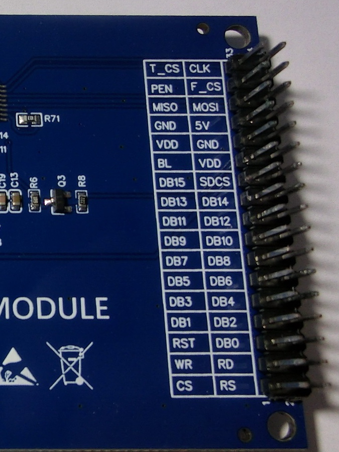
Parallel Interface Signal Lines:
- CS - Output - TFT chip select.
- RS/DC - Output - Data/command control, indicating the type of data currently being transmitted.
- WR - Output - Write strobe for display data.
- RD - Output - Read strobe for display data.
- RESET - Output - Hardware reset for the graphics display controller.
- DB0–DB15 - Output - 16-bit data bus. For 8-bit commands, only the lower byte is used; for graphical data, both bytes are used.
|
|
|
Additional Power and Control Lines (Non-SPI):
- BL - Output - Digital control for the backlight LED. PWM can be used for brightness control. If the backlight is always on, connect to 3.3 V VCC through a pull-up resistor.
- VCC - Power - Connect to a 3.7–5 V supply if the TFT module includes an onboard 3.3 V LDO or regulator; otherwise, connect directly to a 3.3 V supply. Some modules provide a bypass resistor for direct PCB VCC connection. Because TFT displays may draw significant current, using the onboard regulator is recommended when available.
- GND - Power - Ground connection.
- LED - Power - Backlight LED power. A current-limiting resistor may be required.
Optional Peripheral and Auxiliary Lines:
- T_DIN/MOSI - Touch data input/SPI Master Out, Slave In
- T_DO/MISO - Touch data output/SPI Master In, Slave Out
- T_CLK/SCLK - Touch serial clock/SPI serial clock
- T_CS - Touch chip select
- T_IRQ/PEN - Touch interrupt request (microcontroller input, active on touch)
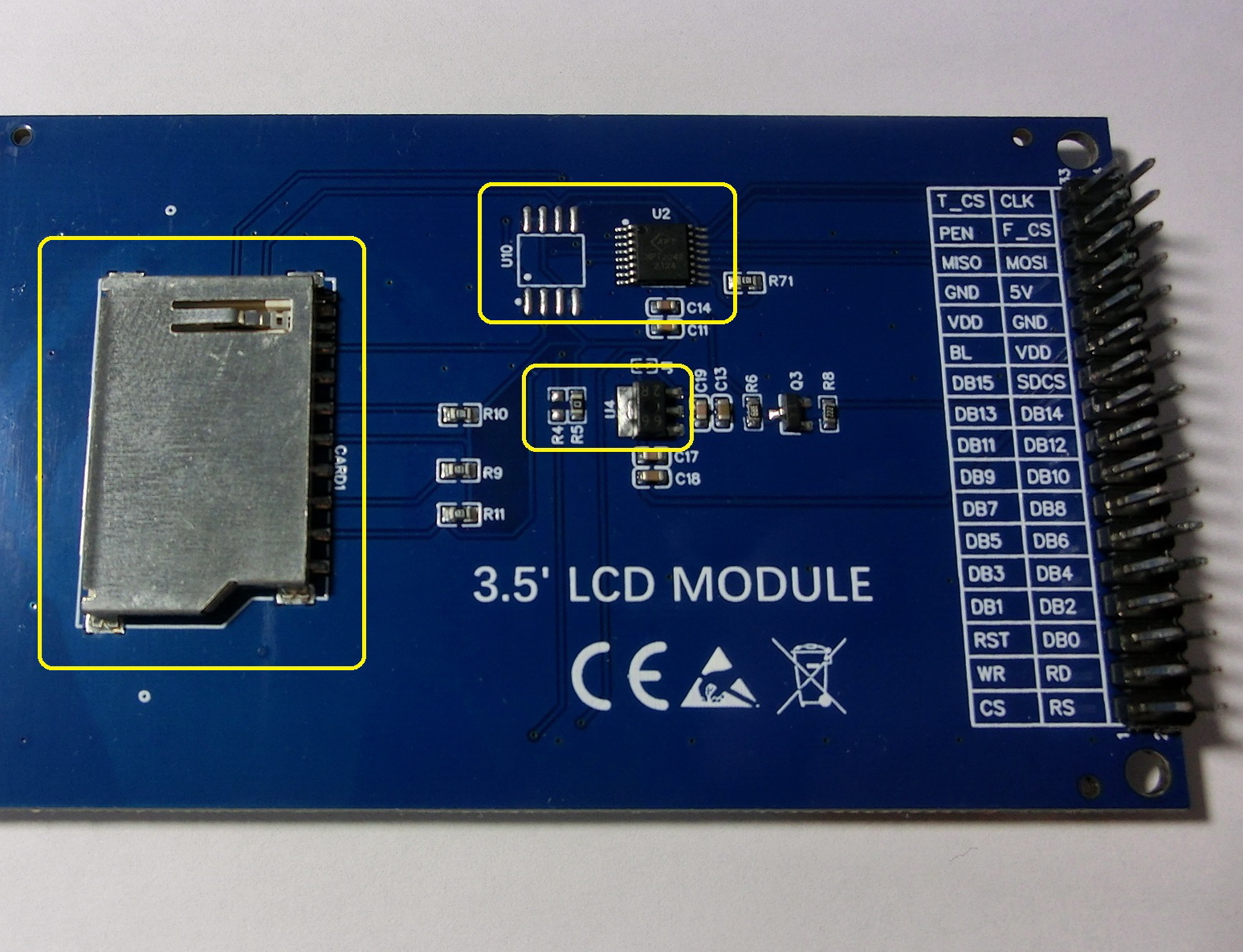
- SD_CS - Output - Chip select for the SD card via SPI, if supported. Not all TFT modules include an SD card slot.
- F_CS - Output - Chip select for the external flash memory via SPI. Some TFT modules provide flash memory pads without a populated IC, allowing a compatible device to be added manually.
|
|
Created with the Personal Edition of HelpNDoc: Upgrade your help files and your workflow with HelpNDoc's WinHelp HLP to CHM conversion

