Isr, EndIsr
Syntax
Isr Interrupt Name, {UnHandled} Interrupt handler BASIC code goes here EndIsr
Overview
Indicate the start and end of an interrupt handling subroutine.
Parameters
Interrupt Name is the name of the interrupt being handled by the subroutine. Unhandled is an optional parameter that will disable context saving and restoring of the WREG SFRs and key SFRs, as well as compiler system variables. Use this option with caution and only when you know that the interrupt handler’s code will not disturb any other SFRs or variables.
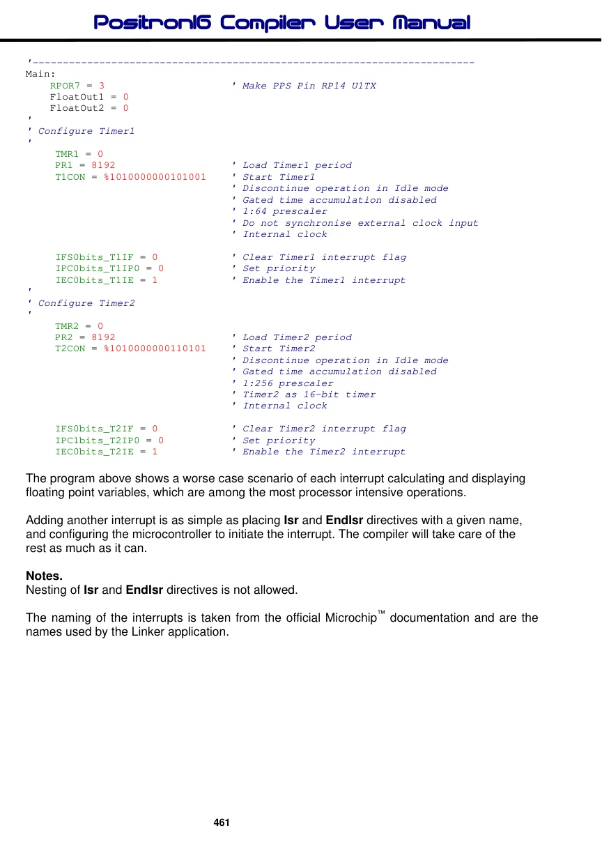
Unlike 8-bit PIC® microcontroller’s, PIC24® and dsPIC33® devices have a separate vector for each type of interrupt. Each interrupt has a specific name, and there are up to 128 of them. A typical interrupt vector name list is shown below:
Interrupt Name Interrupt Cause
| OscillatorFail | Oscillator Failure (Non-Maskable) | |
| StackError | Address Error | (Non-Maskable) |
| AddressError | Stack Error | (Non-Maskable) |
| MathError | Math Error | (Non-Maskable) |
| DMACError | DMA Error | (Non-Maskable) |
| INT0Interrupt | External Interrupt 0 | |
| IC1Interrupt | Input Capture 1 | |
| OC1Interrupt | Output Compare 1 | |
| T1Interrupt | Timer1 | |
| DMA0Interrupt | DMA Channel 0 | |
| IC2Interrupt | Input Capture 2 | |
| OC2Interrupt | Output Compare 2 | |
| T2Interrupt | Timer2 | |
| T3Interrupt | Timer3 | |
| SPI1ErrInterrupt | SPI1 Error | |
| SPI1Interrupt | SPI1 Transfer Done | |
| U1RXInterrupt | UART1 Receiver | |
| U1TXInterrupt | UART1 Transmitter | |
| ADC1Interrupt | ADC 1 | |
| DMA1Interrupt | DMA Channel 1 | |
| SI2C1Interrupt | I2C1 Slave Events | |
| MI2C1Interrupt | I2C1 Master Events | |
| CNInterrupt | Change Notification Interrupt | |
| INT1Interrupt | External Interrupt 1 | |
| IC7Interrupt | Input Capture 7 | |
| IC8Interrupt | Input Capture 8 | |
| DMA2Interrupt | DMA Channel 2 | |
| OC3Interrupt | Output Compare 3 | |
| OC4Interrupt | Output Compare 4 |
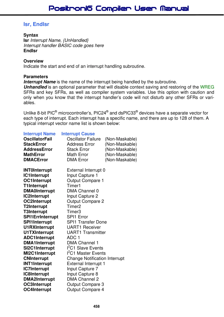
Interrupt Name Interrupt Cause
| T4Interrupt | Timer4 |
| T5Interrupt | Timer5 |
| INT2Interrupt | External Interrupt 2 |
| U2RXInterrupt | UART2 Receiver |
| U2TXInterrupt | UART2 Transmitter |
| SPI2ErrInterrupt | SPI2 Error |
| SPI2Interrupt | SPI1 Transfer Done |
| DMA3Interrupt | DMA Channel 3 |
| IC3Interrupt | Input Capture 3 |
| IC4Interrupt | Input Capture 4 |
| IC5Interrupt | Input Capture 5 |
| IC6Interrupt | Input Capture 6 |
| OC5Interrupt | Output Compare 5 |
| OC6Interrupt | Output Compare 6 |
| OC7Interrupt | Output Compare 7 |
| OC8Interrupt | Output Compare 8 |
| DMA4Interrupt | DMA Channel 4 |
| T6Interrupt | Timer6 |
| T7Interrupt | Timer7 |
| SI2C2Interrupt | I2C2 Slave Events |
| MI2C2Interrupt | I2C2 Master Events |
| T8Interrupt | Timer8 |
| T9Interrupt | Timer9 |
| INT3Interrupt | External Interrupt 3 |
| INT4Interrupt | External Interrupt 4 |
| U1ErrInterrupt | UART1 Error |
| U2ErrInterrupt | UART2 Error |
There are commonalities for the names on all PIC24® and dsPIC33® devices, however, interrupt vector names will be added if the device has a specific peripheral. A full list of the interrupt names for a specific device can be found within the device’s PPI file, under the [ISRSTART] section. The PPI files can be found within the compiler’s “PDS\Includes\PPI” directory.
The first 5 names in the list are interrupts that cannot be disabled. i.e. Non-Maskable, and are used for exception handling within the microcontroller. The others in the list are Maskable, meaning they can be enabled or disabled accordingly.
The interrupt handler, unless otherwise indicated, will first disable any other interrupts, then save key SFRs (Special Function Registers) such as SR (STATUS on 8-bit devices), COR- CON, RCOUNT, WREG0 to WREG14, then if available on the device being used, PSVPAG, DSRPAG, DCOUNT, DOSTART, and DOEND. If the device has more than 65K or code memory, the TBLPAG SFR will also be saved. Saving is accomplished by pushing the SFRs or variables onto the microcontroller’s stack, which will expand to accommodate them.
It will then save any compiler system variables that are used within the interrupt handler, before re-enabling interrupts and handing control to the code within the interrupt handler. The reverse is accomplished when the interrupt is exited, and the Retfie mnemonic issued. Note that the interrupt handler will not reset any associated interrupt flag.
This means that pretty much any BASIC code can be placed inside an interrupt as long as it handles any peripheral conflicts, such as Port re-use etc...
If additional SFRs or variables need to be saved within the interrupt handler, they can by Pushed onto the stack then Popped from it before the interrupt exits. For example:
  Isr T1Interrupt
     Push TRISB                       ' Save 16-bit TRISB on the stack
     Push PORTB                        ' Save 16-bit PORTB on the stack
     Toggle PORTB                   ' Use TRISB and PORTB
     Pop PORTB                         ' Restore 16-bit PORTB from the stack
     Pop TRISB                         ' Restore 16-bit TRISB from the stack
     IFS0bits_T1IF = 0               ' Reset the Timer1 interrupt flag
  EndIsr                              ' Exit the interrupt
Note that the compiler can only track its system variable use when the code is between Isr and EndIsr. It cannot track any code that is called as a subroutine or a procedure from the ISR handler.
An asm Bra mnemonic is placed before the Isr directive, that jumps over the handler code past the EndIsr directive. This means that the interrupt handler can be placed in the line of code without having to jump over it manually. However, this behaviour can be altered by adding a dash after the Isr and EndIsr directives: Isr- and EndIsr-. This will save two bytes of code space for every interrupt handler used in the BASIC program, but measures should be taken to make sure that the program does not run the interrupt code directly, such as a GoTo to the main program loop.
Example
'
' Timer interrupt demo
'
    Device = 24FJ64GA002
    Declare Xtal = 16
    Declare Hserial_Baud = 9600        ' UART1 Baud rate
    Declare Hrsout1_Pin = PORTB.14     ' Select which pin for TX with USART1

    Dim FloatOut1 As Float
    Dim FloatOut2 As Float

'-------------------------------------------------------------------------
    GoTo Main                          ' Jump over the interrupt handlers
'-------------------------------------------------------------------------
' Timer1 interrupt handler
' Transmit a floating point value serially
'
Isr- T1Interrupt                       ' Context save
    HRSOut "Timer1 ", Dec1 FloatOut1, 13
    FloatOut1 = FloatOut1 + 0.1
    IFS0bits_T1IF = 0                  ' Reset the Timer1 interrupt flag
EndIsr-                                ' Context restore and exit the interrupt
'-------------------------------------------------------------------------
' Timer2 interrupt handler
' Transmit a floating point value serially
'
Isr - T2Interrupt                    ' Context save
    HRSOut "Timer2 ", Dec1 FloatOut2, 13
    FloatOut2 = FloatOut2 + 0.1
    IFS0bits_T2IF = 0                  ' Reset the Timer2 interrupt flag
EndIsr-                                ' Context restore and exit the interrupt
'-------------------------------------------------------------------------
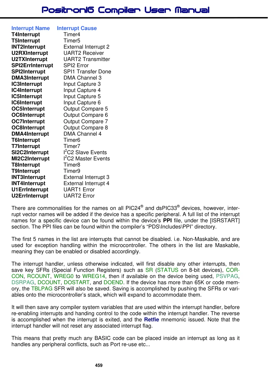
Main:
    RPOR7 = 3                   ' Make PPS Pin RP14 U1TX
    FloatOut1 = 0
    FloatOut2 = 0
'
' Configure Timer1
'
     TMR1 = 0
     PR1 = 8192                   ' Load Timer1 period
     T1CON = %1010000000101001    ' Start Timer1
                                  ' Discontinue operation in Idle mode
                                  ' Gated time accumulation disabled
                                  ' 1:64 prescaler
                                  ' Do not synchronise external clock input
                                  ' Internal clock

     IFS0bits_T1IF = 0            ' Clear Timer1 interrupt flag
     IPC0bits_T1IP0 = 0           ' Set priority
     IEC0bits_T1IE = 1            ' Enable the Timer1 interrupt
'
' Configure Timer2
'
     TMR2 = 0
     PR2 = 8192                   ' Load Timer2 period
     T2CON = %1010000000110101    ' Start Timer2
                                  ' Discontinue operation in Idle mode
                                  ' Gated time accumulation disabled
                                  ' 1:256 prescaler
                                 ' Timer2 as 16-bit timer
                                  ' Internal clock

     IFS0bits_T2IF = 0            ' Clear Timer2 interrupt flag
     IPC1bits_T2IP0 = 0           ' Set priority
     IEC0bits_T2IE = 1            ' Enable the Timer2 interrupt
The program above shows a worse case scenario of each interrupt calculating and displaying floating point variables, which are among the most processor intensive operations.
Adding another interrupt is as simple as placing Isr and EndIsr directives with a given name, and configuring the microcontroller to initiate the interrupt. The compiler will take care of the rest as much as it can.
Notes.
Nesting of Isr and EndIsr directives is not allowed.
The naming of the interrupts is taken from the official Microchip™ documentation and are the names used by the Linker application.