DTMFout
Syntax
DTMFout Pin, { OnTime }, { OffTime, } [ Tone {, Tone…} ]
Overview
Produce a DTMF Touch Tone sequence on Pin.
Parameters
Pin is a Port.Bit constant that specifies the I/O pin to use. This pin will be set to output during generation of tones and set to input after the command is finished. OnTime is an optional variable, constant, or expression (0 - 65535) specifying the duration, in ms, of the tone. If the OnTime parameter is not used, then the default time is 200ms OffTime is an optional variable, constant, or expression (0 - 65535) specifying the length of silent delay, in ms, after a tone (or between tones, if multiple tones are specified). If the OffTime parameter is not used, then the default time is 50ms Tone may be a variable, constant, or expression (0 - 15) specifying the DTMF tone to generate. Tones 0 through 11 correspond to the standard layout of the telephone keypad, while 12 through 15 are the fourth-column tones used by phone test equipment and in some radio applications.
Example
DTMFout PORTA.0, [ 7, 6, 9, 8, 2, 0 ] ' Call a number.If the microcontroller was connected to the phone line correctly, the above command would dial 749990. If you wanted to slow down the dialling in order to break through a noisy phone line or radio link, you could use the optional OnTime and OffTime values: -
'Set the OnTime to 500ms and OffTime to 100ms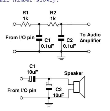
Text in this figure or table
| R1 | R2 |
| 1k | 1k |
To Audio
C1 C2 Amplifier
C1
10uF Speaker
C2 10uF
DTMFout PORTA.0, 500, 100, [7, 6, 9, 8, 2, 0] ' Call number slowly.Notes. DTMF tones are used to dial a telephone, or remotely control pieces of radio equipment. The microcontroller can generate these tones digitally using the
| DTMFout command. However, to achieve the best quality | From I/O pin | |
| tones, a higher crystal frequency is required. A 4MHz | 0.1uF | 0.1uF |
type will work but the quality of the sound produced will suffer. The circuits illustrate how to connect a speaker or audio amplifier to hear the tones produced.
The microcontroller is a digital device, however, DTMF
tones are analogue waveforms, consisting of a mixture of From I/O pin
two sine waves at different audio frequencies. So how can a digital device generate an analogue output? The microcontroller creates and mixes two sine waves mathematically, then uses the resulting stream of numbers to control the duty cycle of an extremely fast pulse-width modulation (PWM) routine. Therefore, what’s actually being produced from the I/O pin is a rapid stream of pulses. The purpose of the filtering arrangements illustrated above is to smooth out the high-frequency PWM, leaving behind only the lower frequency audio. You should keep this in mind if you wish to interface the microcontroller's DTMF output to radios and other equipment that could be adversely affected by the presence of high-frequency noise on the input. Make sure to filter the DTMF output scrupulously. The circuits above are only a reference; you may want to use an active low-pass filter with a cut-off frequency of approximately 2KHz.