SPI (Serial Peripheral Interface)
There are two SPI interface options available for connecting a TFT module: software SPI and hardware SPI. Software SPI uses bit-banging implemented in software, while hardware SPI uses the microcontroller’s dedicated SPI peripheral. Although some modern PIC microcontrollers provide multiple SPI modules, TFT Graphic Library uses only SPI1 or SPI2 when operating in hardware SPI mode.
Some TFT displays use a single bidirectional data line in SPI mode. This behavior is fully supported by the library. When such a display is used and hardware SPI mode is selected, the library transmits data using hardware SPI. When data must be read from the display, the data pin is temporarily reconfigured as an input and the read operation is performed in software SPI mode. After the read completes, the library automatically switches back to hardware SPI output to maintain optimal data transfer speed.
Recommended Design: Whether using Software or Hardware SPI, dedicate the SPI lines to the TFT display whenever possible. Sharing SPI lines with external memory or an SD card significantly reduces the transfer rate between the memory/SD card and the TFT module.
|
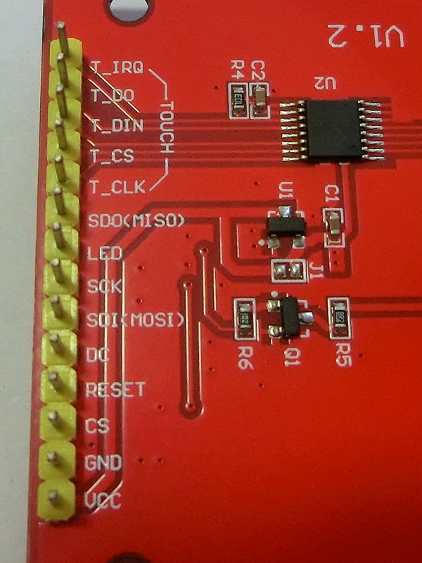
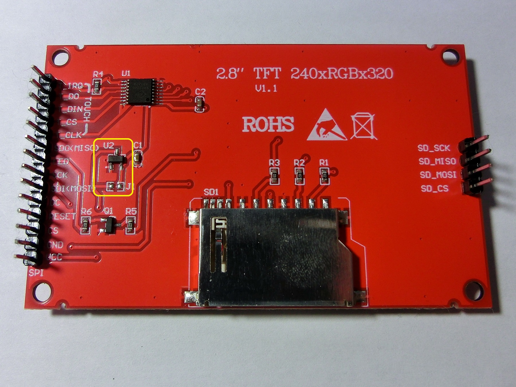
SPI Interface Signal Lines:
(1) Note: Some displays support TFT GRAM pixel readback only via a single data line. Although a MISO pin may be present, it is often not internally connected. In such cases, GRAM readback must be performed in single-line (bidirectional) mode using the MOSI pin. Configure the MISO pin to the same physical pin as MOSI. |
|
|
Additional Power and Control Lines (Non-SPI):
|
|
Created with the Personal Edition of HelpNDoc: Create iPhone web-based documentation