Hrsin, Hrsin2, Hrsin3, Hrsin4
Syntax
Assignment Variable = Hrsin, { Timeout, Timeout Label }
or
Hrsin { Timeout, Timeout Label }, { Parity Error Label }, Modifiers, Variable {, Variable... }
Overview
Receive one or more values from the serial port on devices that contain a hardware USART.
Parameters
Timeout is an optional value for the length of time the Hrsin command will wait before jumping to label Timeout Label. Timeout is specified in 1 millisecond units. Timeout Label is an optional valid BASIC label where Hrsin will jump to in the event that a character has not been received within the time specified by Timeout. Parity Error Label is an optional valid BASIC label where Hrsin will jump to in the event that a Parity error is received. Parity is set using Declares. Parity Error detecting is not supported in the inline version of Hrsin (first syntax example above). Modifier is one of the many formatting modifiers, explained below. Assignment Variable is a user variable, that will be loaded by Hrsin.
Example
' Receive values serially and timeout if no reception after 1 second
'
  Device = 24FJ64GA002           ' Select the device to compile for
  Declare Xtal = 32
  Declare Hserial_Baud = 9600     ' USART1 Baud rate
  Declare Hrsout1_Pin = PORTB.14  ' Select the pin for TX with USART1
  Declare HRSIn1_Pin = PORTB.15  ' Select the pin for RX with USART1

  Dim MyByte as Byte

  CLKDIV = 0                      ' CPU peripheral clock ratio set to 1:1
  Write_OSCCONH(%00010000)        ' Enable PLL
  RPOR7 = 3                      ' Make RP14(PORTB.14) the pin for UART1 TX
  RPINR18 = 15                   ' Make RP15(PORTB.15) the pin for UART1 RX

  Do
     MyByte = Hrsin, {1000, Timeout} ' Receive a byte serially into MyByte
     HrsoutLn Dec MyByte           ' Re-Transmit the byte received
  Loop                           ' Loop forever
Timeout:
  HrsoutLn "Timed Out"           ' Transmit an error if Hrsin timed out
  Stop
'
' For internal oscillator with PLL
'
  Config Config1 = JTAGEN_OFF, GCP_OFF, GWRP_OFF, BKBUG_OFF, COE_OFF,_
                   ICS_PGx1, FWDTEN_OFF, WINDIS_OFF, FWPSA_PR128, WDTPOST_PS256
  Config Config2 = IOL1WAY_OFF, COE_OFF, IESO_OFF, FNOSC_FRCPLL,_
                   FCKSM_CSDCMD, OSCIOFNC_ON, POSCMOD_NONE
Hrsin Modifiers.
As we already know, Rsin will wait for and receive a single byte of data, and store it in a variable . If the microcontroller was connected to a PC running a terminal program and the user pressed the "A" key on the keyboard, after the Hrsin command executed, the variable would contain 65, which is the ASCII code for the letter "A"
What would happen if the user pressed the "1" key? The result would be that the variable would contain the value 49 (the ASCII code for the character "1"). This is an important point to remember: every time you press a character on the keyboard, the computer receives the ASCII value of that character. It is up to the receiving side to interpret the values as necessary. In this case, perhaps we actually wanted the variable to end up with the value 1, rather than the ASCII code 49.
The Hrsin command provides a modifier, called the decimal modifier, which will interpret this for us. Look at the following code: -
Dim SerData as Byte
Hrsin Dec SerData
Notice the decimal modifier in the Hrsin command that appears just to the left of the SerData variable. This tells Hrsin to convert incoming text representing decimal numbers into true decimal form and store the result in SerData. If the user running the terminal software pressed the "1", "2" and then "3" keys followed by a space or other non-numeric text, the value 123 will be stored in the variable SerData, allowing the rest of the program to perform any numeric operation on the variable.
Without the decimal modifier, however, you would have been forced to receive each character ("1", "2" and "3") separately, and then would still have to do some manual conversion to arrive at the number 123 (one hundred twenty three) before you can do the desired calculations on it.
The decimal modifier is designed to seek out text that represents decimal numbers. The characters that represent decimal numbers are the characters "0" through "9". Once the Hrsin command is asked to use the decimal modifier for a particular variable, it monitors the incoming serial data, looking for the first decimal character. Once it finds the first decimal character, it will continue looking for more (accumulating the entire multi-digit number) until is finds a nondecimal numeric character. Remember that it will not finish until it finds at least one decimal character followed by at least one non-decimal character.
To illustrate this further, examine the following examples (assuming we're using the same code example as above): -
Serial input: "ABC" Result: The program halts at the Hrsin command, continuously waiting for decimal text.
Serial input: "123" (with no characters following it) Result: The program halts at the Hrsin command. It recognises the characters "1", "2" and "3" as the number one hundred twenty three, but since no characters follow the "3", it waits continuously, since there's no way to tell whether 123 is the entire number or not.
Serial input: "123" (followed by a space character) Result: Similar to the above example, except once the space character is received, the program knows the entire number is 123, and stores this value in SerData. The Hrsin command then ends, allowing the next line of code to run.
Serial input: "123A" Result: Same as the example above. The "A" character, just like the space character, is the first non-decimal text after the number 123, indicating to the program that it has received the entire number.
Serial input: "ABCD123EFGH" Result: Similar to examples 3 and 4 above. The characters "ABCD" are ignored (since they're not decimal text), the characters "123" are evaluated to be the number 123 and the following character, "E", indicates to the program that it has received the entire number.
The final result of the Dec modifier is limited to 16 bits (up to the value 65535). If a value larger than this is received by the decimal modifier, the end result will be incorrect because the result rolled-over the maximum 16-bit value. Therefore, Hrsin modifiers may not (at this time) be used to load Dword (32-bit) variables.
The decimal modifier is only one of a family of conversion modifiers available with Hrsin See below for a list of available conversion modifiers. All of the conversion modifiers work similar to the decimal modifier (as described above). The modifiers receive bytes of data, waiting for the first byte that falls within the range of characters they accept (e.g., "0" or "1" for binary, "0" to "9" for decimal, "0" to "9" and "A" to "F" for hex. Once they receive a numeric character, they keep accepting input until a non-numeric character arrives, or in the case of the fixed length modifiers, the maximum specified number of digits arrives.
While very effective at filtering and converting input text, the modifiers aren't completely foolproof. As mentioned before, many conversion modifiers will keep accepting text until the first non-numeric text arrives, even if the resulting value exceeds the size of the variable. After Hrsin, a Byte variable will contain the lowest 8 bits of the value entered and a Word (16-bits) would contain the lowest 16 bits. You can control this to some degree by using a modifier that specifies the number of digits, such as Dec2, which would accept values only in the range of 0 to 99.
| Conversion Modifier Type of Number Numeric | Characters Accepted | |
| Dec{1..10} | Decimal, optionally limited | 0 through 9 |
to 1 - 10 digits
| Hex{1..8} | Hexadecimal, optionally limited | 0 through 9, |
| to 1 - 8 digits | A through F | |
| Bin{1..32} | Binary, optionally limited | 0, 1 |
to 1 - 32 digits
A variable preceded by Bin will receive the ASCII representation of its binary value. For example, if Bin Var1 is specified and "1000" is received, Var1 will be set to 8.
A variable preceded by Dec will receive the ASCII representation of its decimal value. For example, if Dec Var1 is specified and "123" is received, Var1 will be set to 123.
A variable preceded by Hex will receive the ASCII representation of its hexadecimal value. For example, if Hex Var1 is specified and "FE" is received, Var1 will be set to 254.
SKIP followed by a count will skip that many characters in the input stream. For example, SKIP 4 will skip 4 characters.
The Hrsin command can be configured to wait for a specified sequence of characters before it retrieves any additional input. For example, suppose a device attached to the microcontroller is known to send many different sequences of data, but the only data you wish to observe happens to appear right after the unique characters, "XYZ". A modifier named Wait can be used for this purpose: -
Hrsin Wait("XYZ"), SerDataThe above code waits for the characters "X", "Y" and "Z" to be received, in that order, then it receives the next data byte and places it into variable SerData.
Str modifier. The Hrsin command also has a modifier for handling a string of characters, named Str.
The Str modifier is used for receiving a string of characters into a byte array variable.
A string is a set of characters that are arranged or accessed in a certain order. The characters "ABC" would be stored in a string with the "A" first, followed by the "B" then followed by the "C". A byte array is a similar concept to a string; it contains data that is arranged in a certain order. Each of the elements in an array is the same size. The string "ABC" would be stored in a byte array containing three bytes (elements).
Below is an example that receives ten bytes and stores them in the 10 element byte array, SerString: -
Dim SerString[10] as Byte    ' Create a 10 element byte array.
Hrsin Str SerString         ' Fill the array with received data.
Print Str SerString         ' Display the string.
If the amount of received characters is not enough to fill the entire array, then a formatter may be placed after the array's name, which will only receive characters until the specified length is reached. For example: -
Dim SerString[10] as Byte       ' Create a 10 element byte array.
Hrsin Str SerString\5         ' Fill the first 5-bytes of the array
Print Str SerString\5         ' Display the 5-character string.
The example above illustrates how to fill only the first n bytes of an array, and then how to display only the first n bytes of the array. n refers to the value placed after the backslash.
Because of its complexity, serial communication can be rather difficult to work with at times. Using the guidelines below when developing a project using the Hrsin and Hrsout commands may help to eliminate some obvious errors: -
Always build your project in steps. Start with small, manageable pieces of code, (that deal with serial communication) and test them, one individually. Add more and more small pieces, testing them each time, as you go. Never write a large portion of code that works with serial communication without testing its smallest workable pieces first.
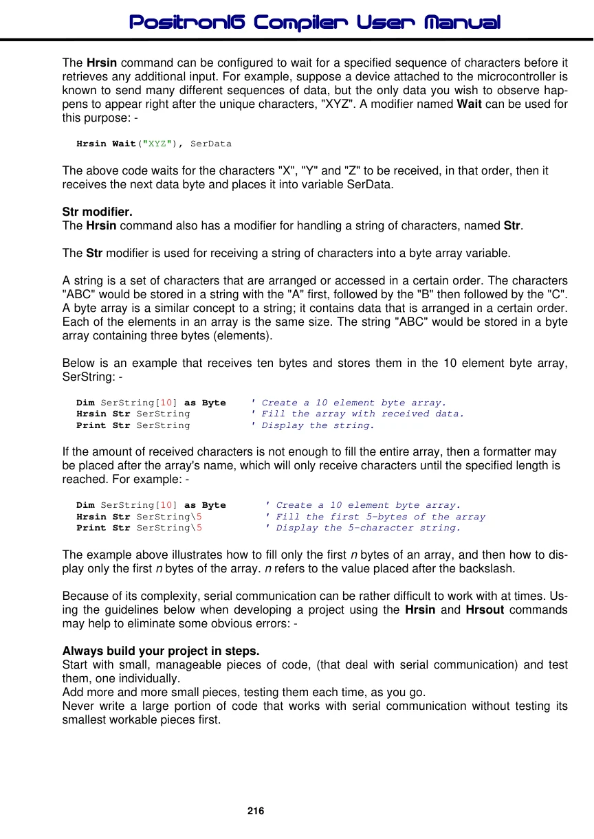
Pay attention to timing. Be careful to calculate and overestimate the amount of time, operations should take within the microcontroller for a given oscillator frequency. Misunderstanding the timing constraints is the source of most problems with code that communicate serially. If the serial communication in your project is bi-directional, the above statement is even more critical.
Pay attention to wiring. Take extra time to study and verify serial communication wiring diagrams. A mistake in wiring can cause strange problems in communication, or no communication at all. Make sure to connect the ground pins (Vss) between the devices that are communicating serially.
Verify port setting on the PC and in the Hrsin / Hrsout commands. Unmatched settings on the sender and receiver side will cause garbled data transfers or no data transfers. This is never more critical than when a line transceiver is used(i.e. MAX232). Always remember that a line transceiver inverts the serial polarity. If the serial data received is unreadable, it is most likely caused by a Baud rate setting error, or a polarity error.
If receiving data from another device that is not a microcontroller, try to use Baud rates of 9600 and below, or alternatively, use a higher frequency crystal.
Because of additional overheads in the microcontroller, and the fact that the Hrsin command only offers a 8 level receive buffer for serial communication, received data may sometimes be missed or garbled. If this occurs, try lowering the Baud rate, or increasing the crystal frequency. Using simple variables (not arrays) will also increase the chance that the microcontroller will receive the data properly.
Declares
There are several Declare directives for use with the Hrsin commands. These are: -
Declare HRsin_Pin Port.Pin Declares the port and pin used for USART1 reception (RX). The location of the port and pin is dictated by the device's PPS (Peripheral Pin Select) options. Note that this declare will not alter any PPS (Peripheral Pin Select) SFRs.
Declare Hserial_Baud Constant value Sets the Baud rate that will be used to receive a value serially from USART1. The Baud rate is calculated using the Xtal frequency declared in the program. The default Baud rate if the Declare is not included in the program listing is 9600 Baud.
Declare Hserial_Parity Odd or Even Enables/Disables parity on the serial port. For both Hrsin and Hrsout The default serial data format is 8N1, 8 data bits, no parity bit and 1 stop bit. 7E1 (7 data bits, even parity, 1 stop bit) or 7O1 (7data bits, odd parity, 1 stop bit) may be enabled using the Hserial_Parity declare.
Declare Hserial_Parity = Even    ' Use if even parity desired
Declare Hserial_Parity = Odd    ' Use if odd parity desired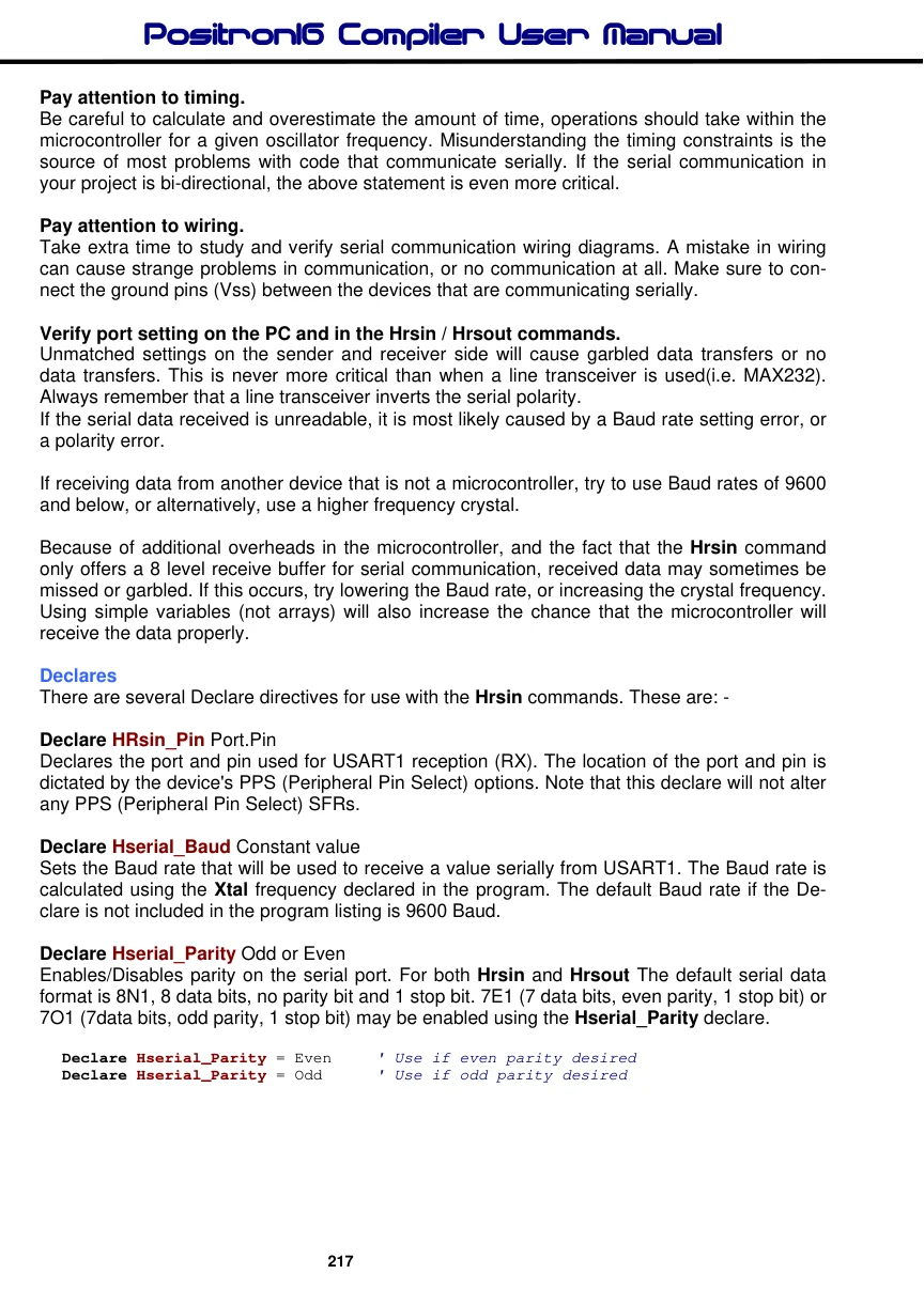
Declare Hserial_Clear On or Off Clear the overflow error bit before commencing a read.
The hardware serial ports (USARTs) only have a small input buffer, therefore, they can easily overflow if characters are not read from it often enough. When this occurs, USART1 stops accepting any new characters, and requires resetting. This overflow error can be reset by clearing the OERR bit within the U1STA register:
Clear U1STAbits_OERR ' Clear an overflow error for USART1Alternatively, the Hserial_Clear declare can be used to automatically clear this error, even if no error occurred. However, the program will not know if an error occurred while reading, therefore some characters may be lost.
Declare Hserial_Clear = OnDeclare HRsin2_Pin Port.Pin Declares the port and pin used for USART2 reception (RX). The location of the port and pin is dictated by the device's PPS (Peripheral Pin Select) options. Note that this declare will not alter any PPS (Peripheral Pin Select) SFRs.
Declare Hserial2_Baud Constant value Sets the Baud rate that will be used to receive a value serially from USART2. The Baud rate is calculated using the Xtal frequency declared in the program. The default Baud rate if the Declare is not included in the program listing is 9600 Baud.
Declare Hserial2_Parity Odd or Even Enables/Disables parity on the serial port. For both Hrsin2 and Hrsout2 The default serial data format is 8N1, 8 data bits, no parity bit and 1 stop bit. 7E1 (7 data bits, even parity, 1 stop bit) or 7O1 (7data bits, odd parity, 1 stop bit) may be enabled using the Hserial2_Parity declare.
Declare Hserial2_Parity = Even    ' Use if even parity desired
Declare Hserial2_Parity = Odd    ' Use if odd parity desired
Declare Hserial2_Clear On or Off Clear the overflow error bit before commencing a read.
The hardware serial ports (USARTs) only have a small input buffer, therefore, they can easily overflow if characters are not read from it often enough. When this occurs, USART2 stops accepting any new characters, and requires resetting. This overflow error can be reset by clearing the OERR bit within the U2STA register:
Clear U2STAbits_OERR ' Clear an overflow error for USART2Alternatively, the Hserial2_Clear declare can be used to automatically clear this error, even if no error occurred. However, the program will not know if an error occurred while reading, therefore some characters may be lost.
Declare Hserial2_Clear = On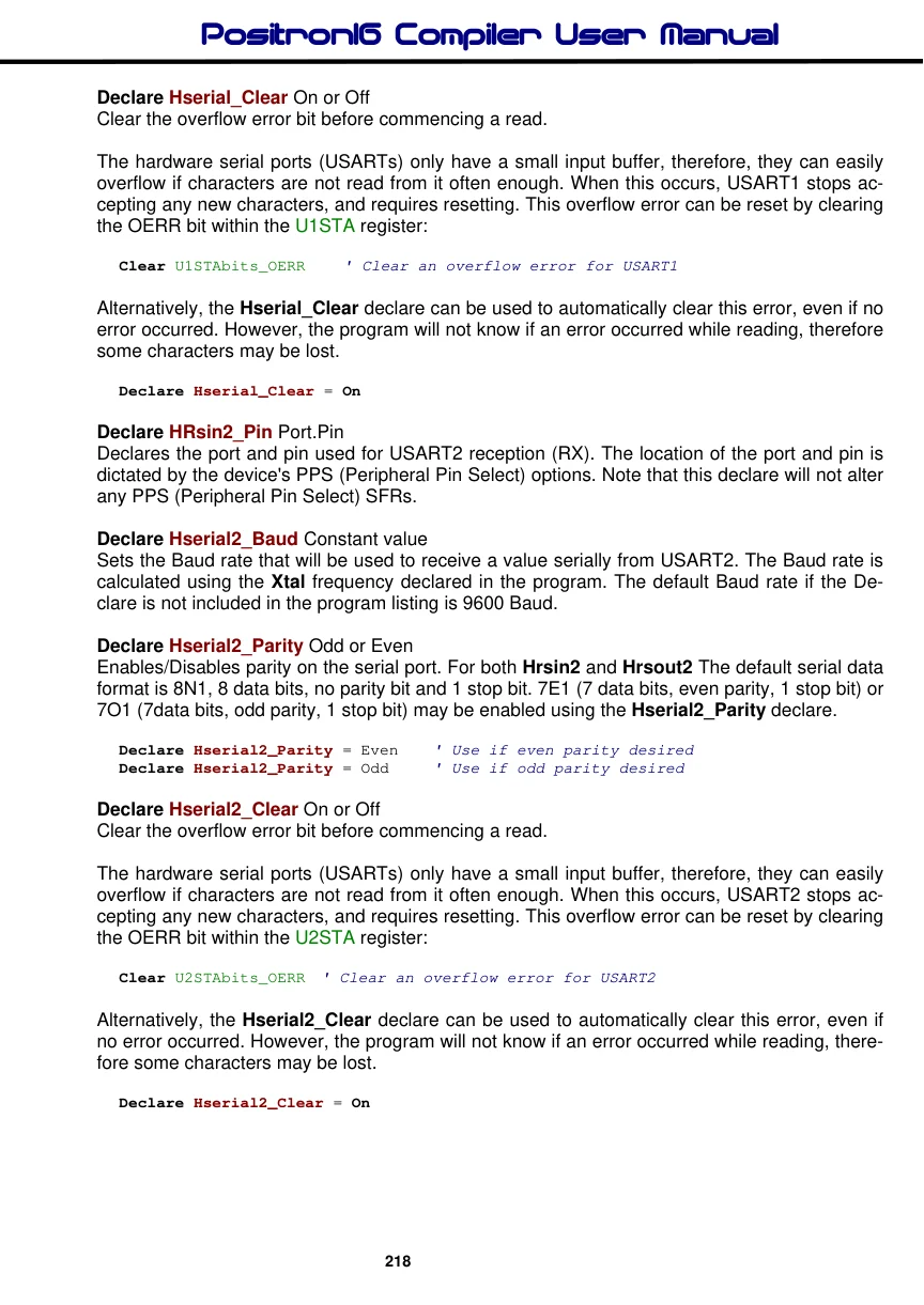
Declare HRsin3_Pin Port.Pin Declares the port and pin used for USART3 reception (RX). The location of the port and pin is dictated by the device's PPS (Peripheral Pin Select) options. Note that this declare will not alter any PPS (Peripheral Pin Select) SFRs.
Declare Hserial3_Baud Constant value Sets the Baud rate that will be used to receive a value serially from USART3. The Baud rate is calculated using the Xtal frequency declared in the program. The default Baud rate if the Declare is not included in the program listing is 9600 Baud.
Declare Hserial3_Parity Odd or Even Enables/Disables parity on the serial port. For both Hrsin3 and Hrsout3 The default serial data format is 8N1, 8 data bits, no parity bit and 1 stop bit. 7E1 (7 data bits, even parity, 1 stop bit) or 7O1 (7data bits, odd parity, 1 stop bit) may be enabled using the Hserial3_Parity declare.
 Declare Hserial3_Parity = Even   ' Use if even parity desired
 Declare Hserial3_Parity = Odd    ' Use if odd parity desired
Declare Hserial3_Clear On or Off Clear the overflow error bit before commencing a read.
The hardware serial ports (USARTs) only have a small input buffer, therefore, they can easily overflow if characters are not read from it often enough. When this occurs, USART3 stops accepting any new characters, and requires resetting. This overflow error can be reset by clearing the OERR bit within the U3STA register:
Clear U3STAbits_OERR ' Clear an overflow error for USART3Alternatively, the Hserial3_Clear declare can be used to automatically clear this error, even if no error occurred. However, the program will not know if an error occurred while reading, therefore some characters may be lost.
Declare Hserial3_Clear = OnDeclare HRsin4_Pin Port.Pin Declares the port and pin used for USART4 reception (RX). The location of the port and pin is dictated by the device's PPS (Peripheral Pin Select) options. Note that this declare will not alter any PPS (Peripheral Pin Select) SFRs.
Declare Hserial4_Baud Constant value Sets the Baud rate that will be used to receive a value serially from USART4. The Baud rate is calculated using the Xtal frequency declared in the program. The default Baud rate if the Declare is not included in the program listing is 9600 Baud.
Declare Hserial4_Parity Odd or Even Enables/Disables parity on the serial port. For both Hrsin4 and Hrsout4 The default serial data format is 8N1, 8 data bits, no parity bit and 1 stop bit. 7E1 (7 data bits, even parity, 1 stop bit) or 7O1 (7data bits, odd parity, 1 stop bit) may be enabled using the Hserial4_Parity declare.
Declare Hserial4_Parity = Even  ' Use if even parity desired
Declare Hserial4_Parity = Odd    ' Use if odd parity desired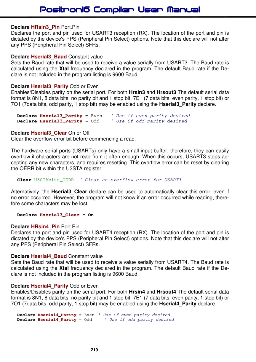
Declare Hserial4_Clear On or Off Clear the overflow error bit before commencing a read.
The hardware serial ports (USARTs) only have a small input buffer, therefore, they can easily overflow if characters are not read from it often enough. When this occurs, USART4 stops accepting any new characters, and requires resetting. This overflow error can be reset by clearing the OERR bit within the U4STA register:
Clear U4STAbits_OERR ' Clear an overflow error for USART4Alternatively, the Hserial4_Clear declare can be used to automatically clear this error, even if no error occurred. However, the program will not know if an error occurred while reading, therefore some characters may be lost.
Declare Hserial4_Clear = OnNotes.
The Hrsin commands can only be used with devices that contain a hardware USART. See the specific device's data sheet for further information concerning the serial input pin as well as other relevant parameters.