Using a KS0108 Graphic LCD
Once a KS0108 graphic LCD has been chosen using the Declare LCD_Type directive, all Print outputs will be directed to that LCD.
The standard modifiers used by an alphanumeric LCD may also be used with the graphics LCD. Most of the above modifiers still work in the expected manner, however, the At modifier now starts at Ypos 0 and Xpos 0, where values 0,0 will be the top left corner of the LCD.
There are also four new modifiers. These are: -
| Font 0 to n | Choose the nth font, if available |
| Inverse 0-1 | Invert the characters sent to the LCD |
| or 0-1 | Or the new character with the original |
| Xor 0-1 | Xor the new character with the original |
Once one of the four new modifiers has been enabled, all future Print commands will use that particular feature until the modifier is disabled. For example: -
' Enable inverted characters from this point
  Print At 0, 0, Inverse 1, "Hello World"
  Print At 1, 0, "Still Inverted"
' Now use normal characters
  Print At 2, 0, Inverse 0, "Normal Characters"
If no modifiers are present, then the character's ASCII representation will be displayed: -
' Print characters A and B
  Print At 0, 0, 65, 66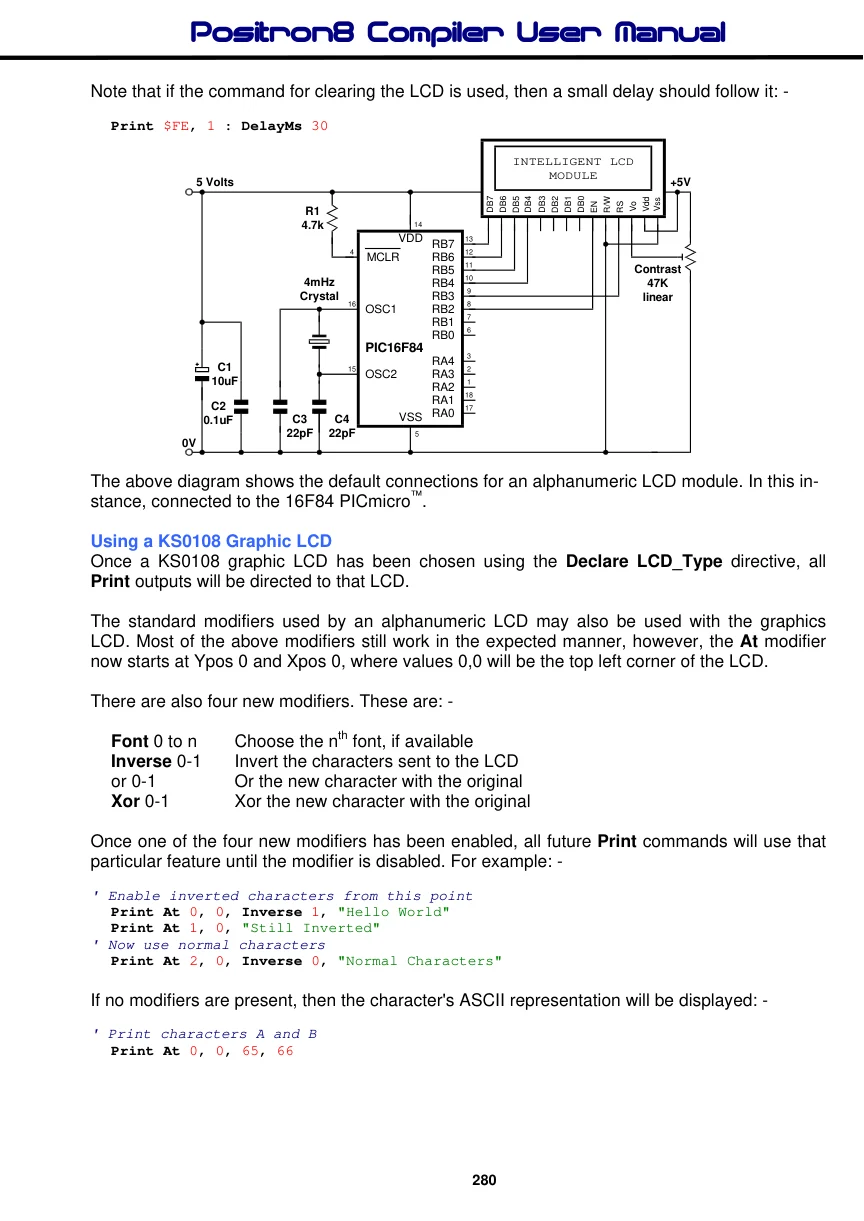
Declares
There are nine declares associated with a KS0108 graphic LCD.
Declare LCD_DTPort Port Assign the port that will output the 8-bit data to the graphic LCD.
If the Declare is not used, then the default port is PORTD.
Declare LCD_RWPin Port.Pin Assigns the Port and Pin that the graphic LCD's RW line will attach to.
If the Declare is not used in the program, then the default Port and Pin is PORTE.0.
Declare LCD_CS1Pin Port.Pin Assigns the Port and Pin that the graphic LCD's CS1 line will attach to.
If the Declare is not used in the program, then the default Port and Pin is PORTC.0.
Declare LCD_CS2Pin Port.Pin Assigns the Port and Pin that the graphic LCD's CS2 line will attach to.
If the Declare is not used in the program, then the default Port and Pin is PORTC.2.
Note
Along with the new declares, two of the existing LCD declares must also be used. Namely, RS_Pin and EN_Pin.
Declare Internal_Font On - Off, 1 or 0 The graphic LCDs that are compatible with compiler’s built-in library routines are non-intelligent types, therefore, a separate character set is required. This may be in one of two places, either externally, in an I2C EEPROM, or internally in a Cdata table.
If the Declare is omitted from the program, then an external font is the default setting.
If an external font is chosen, the I2C EEPROM must be connected to the specified SDA and SCL pins (as dictated by Declare SDA and Declare SCL).
If an internal font is chosen, it must be on a PICmicro™ device that has self modifying code features, such as the 16F87X range.
The Cdata table that contains the font must have a label, named Font_Table: preceding it. For example: -
Font_Table:- '{ data for characters 0 to 64 }
     Cdata $7E, $11, $11, $11, $7E, $00,_  ' Chr 65 "A"
           $7F, $49, $49, $49, $36, $00   ' Chr 66 "B"
     { rest of font table }
Notice the dash after the font's label, this disables any bank switching code that may otherwise disturb the location in memory of the Cdata table.
The font table may be anywhere in memory, however, it is best placed after the main program code.

Text in this figure or table
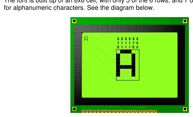
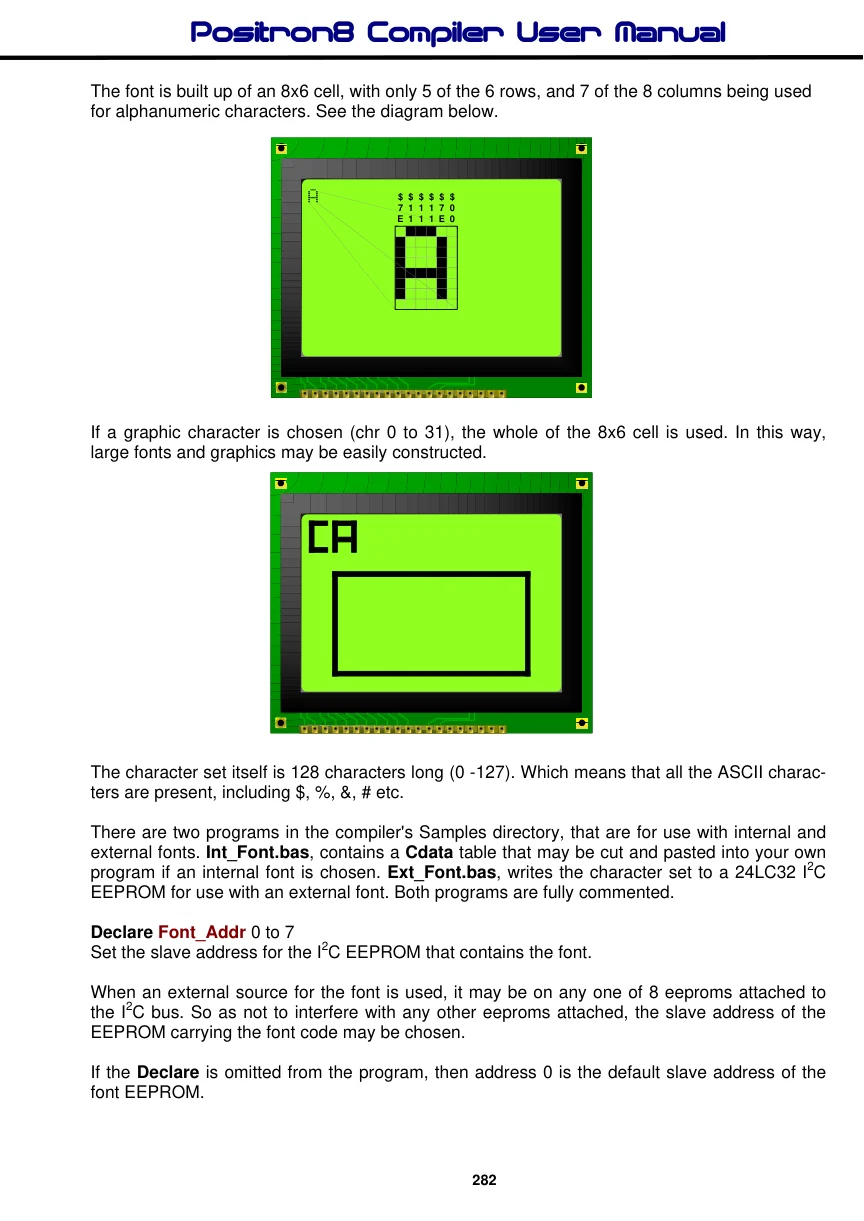
for alphanumeric characters. See the diagram below.
$ $ $ $ $ $ 7 1 1 1 7 0 E 1 1 1 E 0
The font is built up of an 8x6 cell, with only 5 of the 6 rows, and 7 of the 8 columns being used
Text in this figure or table
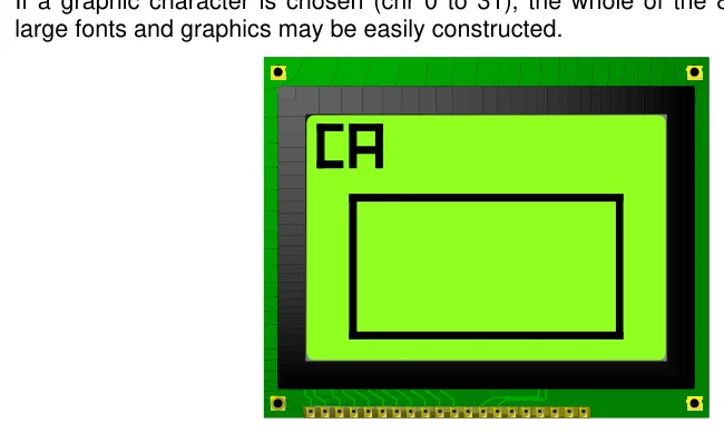
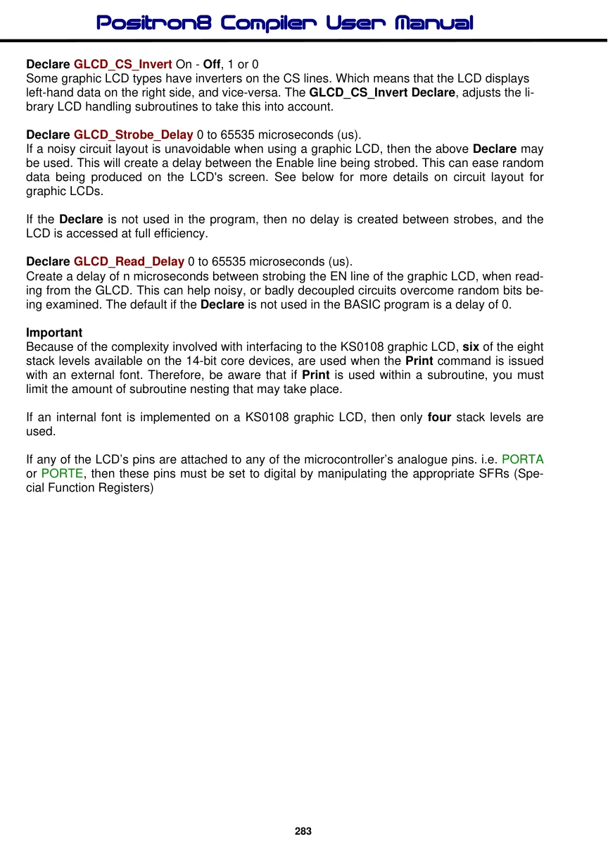
large fonts and graphics may be easily constructed.
If a graphic character is chosen (chr 0 to 31), the whole of the 8x6 cell is used. In this way,
The character set itself is 128 characters long (0 -127). Which means that all the ASCII characters are present, including $, %, &, # etc.
There are two programs in the compiler's Samples directory, that are for use with internal and external fonts. Int_Font.bas, contains a Cdata table that may be cut and pasted into your own program if an internal font is chosen. Ext_Font.bas, writes the character set to a 24LC32 I2C EEPROM for use with an external font. Both programs are fully commented.
Declare Font_Addr 0 to 7 Set the slave address for the I2C EEPROM that contains the font.
When an external source for the font is used, it may be on any one of 8 eeproms attached to the I2C bus. So as not to interfere with any other eeproms attached, the slave address of the EEPROM carrying the font code may be chosen.
If the Declare is omitted from the program, then address 0 is the default slave address of the font EEPROM.
Declare GLCD_CS_Invert On - Off, 1 or 0 Some graphic LCD types have inverters on the CS lines. Which means that the LCD displays left-hand data on the right side, and vice-versa. The GLCD_CS_Invert Declare, adjusts the library LCD handling subroutines to take this into account.
Declare GLCD_Strobe_Delay 0 to 65535 microseconds (us). If a noisy circuit layout is unavoidable when using a graphic LCD, then the above Declare may be used. This will create a delay between the Enable line being strobed. This can ease random data being produced on the LCD's screen. See below for more details on circuit layout for graphic LCDs.
If the Declare is not used in the program, then no delay is created between strobes, and the LCD is accessed at full efficiency.
Declare GLCD_Read_Delay 0 to 65535 microseconds (us). Create a delay of n microseconds between strobing the EN line of the graphic LCD, when reading from the GLCD. This can help noisy, or badly decoupled circuits overcome random bits being examined. The default if the Declare is not used in the BASIC program is a delay of 0.
Important Because of the complexity involved with interfacing to the KS0108 graphic LCD, six of the eight stack levels available on the 14-bit core devices, are used when the Print command is issued with an external font. Therefore, be aware that if Print is used within a subroutine, you must limit the amount of subroutine nesting that may take place.
If an internal font is implemented on a KS0108 graphic LCD, then only four stack levels are used.
If any of the LCD’s pins are attached to any of the microcontroller’s analogue pins. i.e. PORTA or PORTE, then these pins must be set to digital by manipulating the appropriate SFRs (Special Function Registers)
Text in this figure or table
   128x64
SAMSUNG KS0108
 GRAPHIC LCD
5 Volts -VoutRST CS2 CS1 DB7 DB6 DB5DB4 DB3DB2 DB1DB0 ENR/W RS Vo VccGnd
| 5 Volts | 1k |
| 18 | 1 |
| 11 | 32 |
Contrast 10
VDD VDD RE2 47k
9 RE1 8 RE0
R1 30
RD7
4.7k 29
RD6 28 RD5
| 1 | 27 |
| MCLR | RD4 |
22 RD3 21 RD2 20 RD1
C1 19
RD0 10uF C2 0.1uF 24 RC5 23 RC4 18 RC3 17 RC2 5 Volts PIC16F877
| 20MHz | 2x | 8 |
| Crystal | 4.7k |
VCC 13
OSC1 7
WP 5 SDA 6 SCL 1
| 14 | A0 |
| OSC2 | 2 |
| 24LC32 | A1 |
3 A2 VSS
C3 C4
VSSVSS
| 15pF 15pF | 4 |
| 12 | 31 |
0V
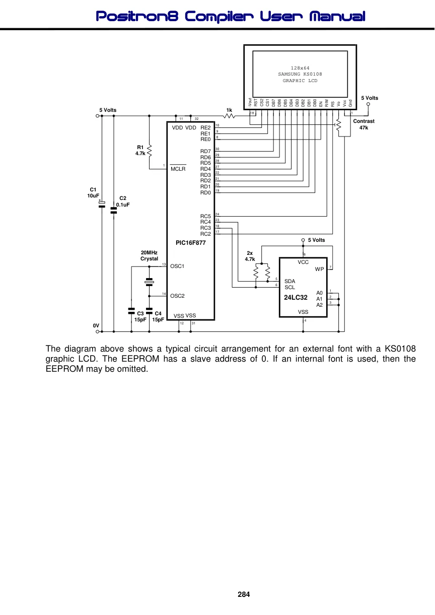
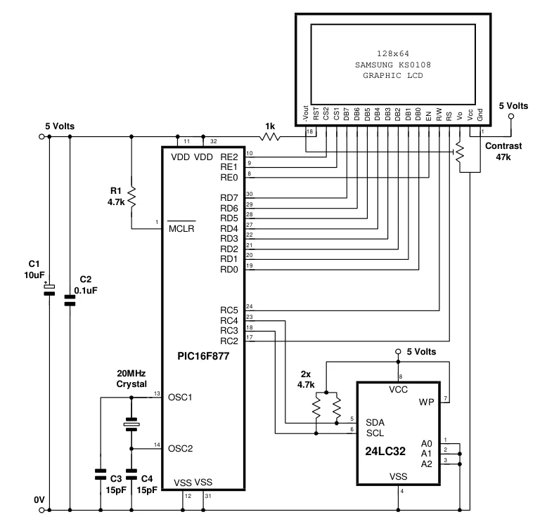
The diagram above shows a typical circuit arrangement for an external font with a KS0108 graphic LCD. The EEPROM has a slave address of 0. If an internal font is used, then the EEPROM may be omitted.