HPWM
Syntax
HPWM Channel, DutyCycle, Frequency
Overview
Output a pulse width modulated pulse train using the CCP modules PWM (Pulse Width Modulation) hardware, available on some microcontrollers. The PWM pulses produced can run continuously in the background while the program is executing other instructions.
Parameters
Channel is a constant value that specifies which hardware PWM channel to use. Some devices have 1, 2 or 3 PWM channels. On devices with 2 channels, the Frequency must be the same on both channels. It must be noted, that this is a limitation of the PICmicro™ not the compiler. The data sheet for the particular device used shows the fixed hardware pin for each Channel. For example, for a PIC16F877, Channel 1 is CCP1 which is pin PORTC.2. Channel 2 is CCP2 which is pin PORTC.1. DutyCycle is a variable, constant (0-255), or expression that specifies the on/off (high/low) ratio of the signal. It ranges from 0 to 255, where 0 is off (low all the time) and 255 is on (high) all the time. A value of 127 gives a 50% duty cycle (square wave). Frequency is a variable, constant (0-32767), or expression that specifies the desired frequency of the PWM signal. Not all frequencies are available at all oscillator settings. The highest frequency at any oscillator speed is 32767Hz. The lowest usable HPWM Frequency at each oscillator setting is shown in the table below: -
| Xtal frequency | Lowest useable PWM frequency |
| 4MHz | 145Hz |
| 8MHz | 489Hz |
| 10MHz | 611Hz |
| 12MHz | 733Hz |
| 16MHz | 977Hz |
| 20MHz | 1221Hz |
| 24MHz | 1465Hz |
| 33MHz | 2015Hz |
| 40MHz | 2442Hz |
Example
Device = 18F26K40   ' Select the device to compile for
Declare Xtal = 16  ' Tell the compiler the device will be operating at 16MHz

HPWM 1, 127, 1000    ' Send a 50% duty cycle PWM signal at 1KHz
DelayMs 500
HPWM 1, 64, 2000    ' Send a 25% duty cycle PWM signal at 2KHz
Stop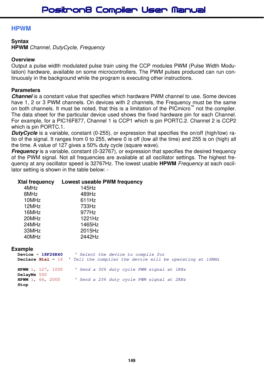
Notes
Some devices have alternate pins that may be used for HPWM. The following Declares allow the use of different pins: -
Declare CCP1_Pin Port.Pin ' Select HPWM port and bit for CCP1 module (ch 1)
Declare CCP2_Pin Port.Pin ' Select HPWM port and bit for CCP2 module (ch 2)
Declare CCP3_Pin Port.Pin ' Select HPWM port and bit for CCP3 module (ch 3)
Declare CCP4_Pin Port.Pin ' Select HPWM port and bit for CCP4 module (ch 4)
Declare CCP5_Pin Port.Pin ' Select HPWM port and bit for CCP5 module (ch 5)
Declare CCP6_Pin Port.Pin ' Select HPWM port and bit for CCP6 module (ch 6)
Or
Declare HPWM1_Pin Port.Pin ' Select HPWM port and bit for PWM1 module (ch 1)
Declare HPWM2_Pin Port.Pin ' Select HPWM port and bit for PWM 2 module (ch 2)
Declare HPWM3_Pin Port.Pin ' Select HPWM port and bit for PWM 3 module (ch 3)
Declare HPWM4_Pin Port.Pin ' Select HPWM port and bit for PWM 4 module (ch 4)
Declare HPWM5_Pin Port.Pin ' Select HPWM port and bit for PWM 5 module (ch 5)
Declare HPWM6_Pin Port.Pin ' Select HPWM port and bit for PWM 6 module (ch 6)
Both texts after the declare; HPWMx_Pin or CCPx_Pin are valid for all devices that contain, either CCP peripherals or PWM peripherals.
For devices that have PPS (Peripheral Pin Select), the compiler will manipulate the appropriate SFRs before the program starts, so that the PWM signal is produced correctly.
