PWM
Syntax
PWM Pin, Duty, Cycles
Overview
Output pulse-width-modulation on a pin, then return the pin to input state.
Parameters
Pin is a Port.Pin constant that specifies the I/O pin to use. Duty is a variable, constant (0-255), or expression, which specifies the analogue level desired (0-5 volts). Cycles is a variable or constant (0-255) which specifies the number of cycles to output. Larger capacitors require multiple cycles to fully charge. Cycle time is dependant on Xtal frequency. If a 4MHz crystal is used, then cycle takes approx 5 ms. If a 20MHz crystal is used, then cycle takes approx 1 ms.
Notes
PWM can be used to generate analogue voltages (0-5V) through a pin connected to a resistor and capacitor to ground; the resistor-capacitor junction is the analogue output (see circuit). Since the capacitor gradually discharges, PWM should be executed periodically to refresh the
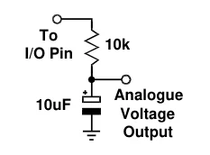
analogue voltage.
PWM emits a burst of 1s and 0s whose ratio is proportional to the duty 10k
value you specify. If duty is 0, then the pin is continuously low (0); if
| duty is 255, then the pin is continuously high. For values in between, | Analogue |
| the proportion is duty/255. For example, if duty is 100, the ratio of 1s to | Voltage |
0s is 100/255 = 0.392, approximately 39 percent.
When such a burst is used to charge a capacitor arranged, the voltage across the capacitor is equal to:-
(duty / 255) * 5.
So if duty is 100, the capacitor voltage is
(100 / 255) * 5 = 1.96 volts.
Text in this figure or table
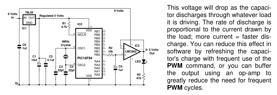
This voltage will drop as the capaci- 9 Volts 78L05 9 Volts
| Regulated 5 Volts | tor discharges through whatever load | |
| In | IN OUT | |
| GND | R1 | it is driving. The rate of discharge is |
IC2 14 4.7k IC1
VDD 13 proportional to the current drawn by
RB7
| 4 | 12 |
| MCLR | RB6 |
11
RB5 the load; more current = faster dis-
10
| 4MHz | RB4 | |||
| 9 | 8 | |||
| C6 | Crystal | RB3 | IC3 | charge. You can reduce this effect in |
| 16 | 8 | 2 | ||
| .1uf | OSC1 | RB2 | R2 | - |
| 7 | 1 | 0- 5 Volts | ||
| RB1 | 10k | LMC662 | software by refreshing the capaci- | |
| 6 | 3 | Out | ||
| RB0 | + | |||
| C1 | C2 | |||
| PIC16F84 | 4 | |||
| 10uf | 0.1uf | 3 | tor's charge with frequent use of the | |
| RA4 | LED | |||
| 14 | 2 | |||
| OSC2 | RA3 | |||
| C3 | C4 | 1 | C5 | PWM command, or you can buffer |
RA2
| 18 | 1uf | |
| 22pf | 22pf | RA1 |
| 17 | the output using an op-amp to | |
| RA0 | R3 |
VSS 470 5 greatly reduce the need for frequent 0v PWM cycles.