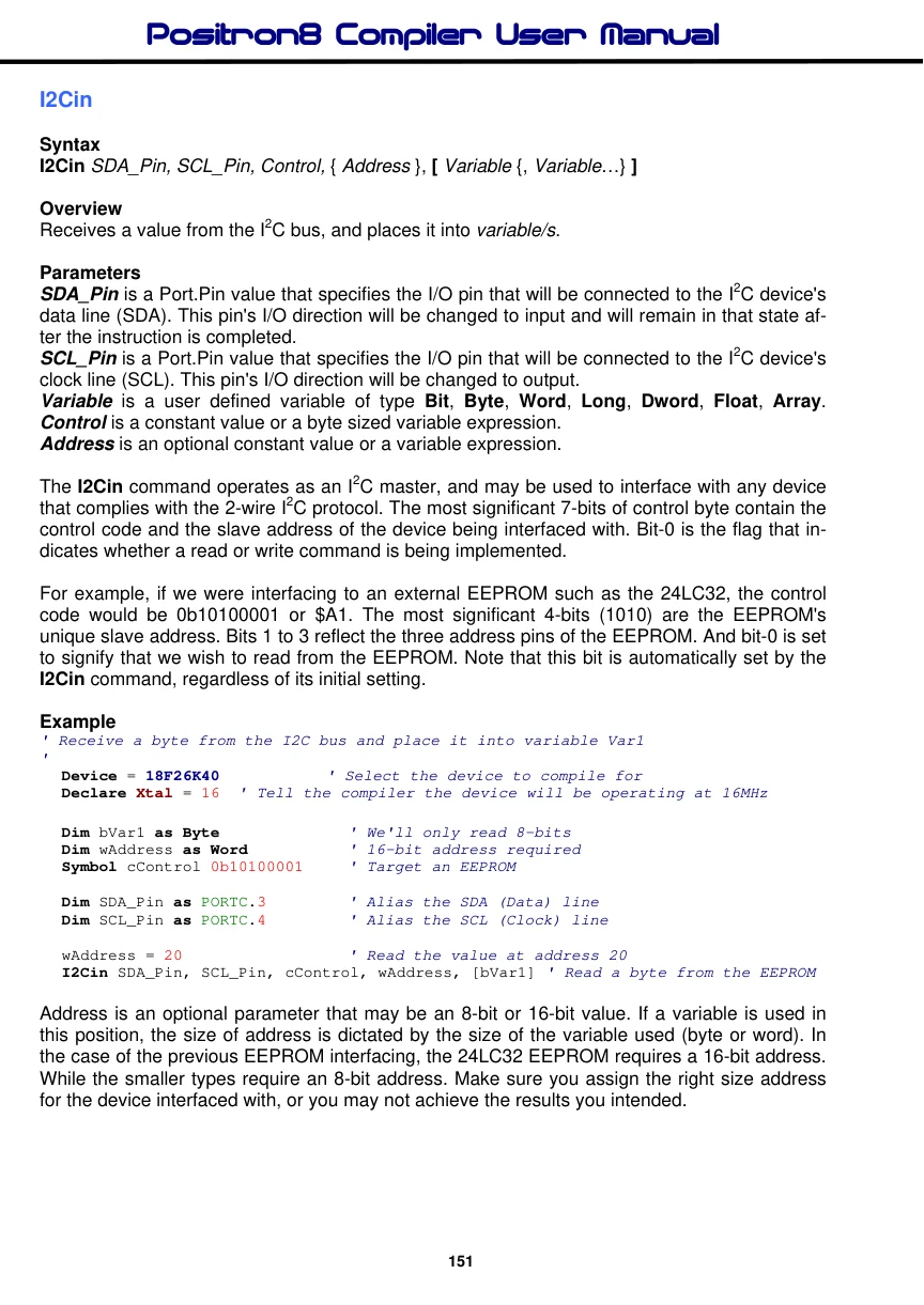
I2Cin
Syntax
I2Cin SDA_Pin, SCL_Pin, Control, { Address }, [ Variable {, Variable…} ]
Overview
Receives a value from the I2C bus, and places it into variable/s.
Parameters
SDA_Pin is a Port.Pin value that specifies the I/O pin that will be connected to the I2C device's data line (SDA). This pin's I/O direction will be changed to input and will remain in that state after the instruction is completed. SCL_Pin is a Port.Pin value that specifies the I/O pin that will be connected to the I2C device's clock line (SCL). This pin's I/O direction will be changed to output. Variable is a user defined variable of type Bit, Byte, Word, Long, Dword, Float, Array. Control is a constant value or a byte sized variable expression. Address is an optional constant value or a variable expression.
The I2Cin command operates as an I2C master, and may be used to interface with any device that complies with the 2-wire I2C protocol. The most significant 7-bits of control byte contain the control code and the slave address of the device being interfaced with. Bit-0 is the flag that indicates whether a read or write command is being implemented.
For example, if we were interfacing to an external EEPROM such as the 24LC32, the control code would be 0b10100001 or $A1. The most significant 4-bits (1010) are the EEPROM's unique slave address. Bits 1 to 3 reflect the three address pins of the EEPROM. And bit-0 is set to signify that we wish to read from the EEPROM. Note that this bit is automatically set by the I2Cin command, regardless of its initial setting.
Example
' Receive a byte from the I2C bus and place it into variable Var1
'
  Device = 18F26K40          ' Select the device to compile for
  Declare Xtal = 16  ' Tell the compiler the device will be operating at 16MHz

  Dim bVar1 as Byte              ' We'll only read 8-bits
  Dim wAddress as Word           ' 16-bit address required
  Symbol cControl 0b10100001     ' Target an EEPROM

  Dim SDA_Pin as PORTC.3        ' Alias the SDA (Data) line
  Dim SCL_Pin as PORTC.4        ' Alias the SCL (Clock) line

  wAddress = 20                   ' Read the value at address 20
  I2Cin SDA_Pin, SCL_Pin, cControl, wAddress, [bVar1] ' Read a byte from the EEPROM
Address is an optional parameter that may be an 8-bit or 16-bit value. If a variable is used in this position, the size of address is dictated by the size of the variable used (byte or word). In the case of the previous EEPROM interfacing, the 24LC32 EEPROM requires a 16-bit address. While the smaller types require an 8-bit address. Make sure you assign the right size address for the device interfaced with, or you may not achieve the results you intended.
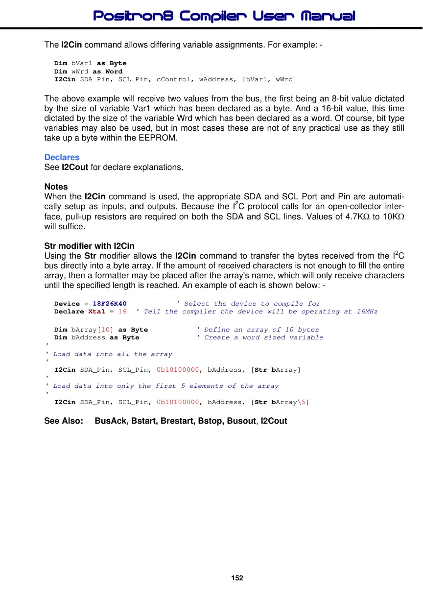
The I2Cin command allows differing variable assignments. For example: -
Dim bVar1 as Byte
Dim wWrd as Word
I2Cin SDA_Pin, SCL_Pin, cControl, wAddress, [bVar1, wWrd]
The above example will receive two values from the bus, the first being an 8-bit value dictated by the size of variable Var1 which has been declared as a byte. And a 16-bit value, this time dictated by the size of the variable Wrd which has been declared as a word. Of course, bit type variables may also be used, but in most cases these are not of any practical use as they still take up a byte within the EEPROM.
Declares
See I2Cout for declare explanations.
Notes
When the I2Cin command is used, the appropriate SDA and SCL Port and Pin are automatically setup as inputs, and outputs. Because the I2C protocol calls for an open-collector interface, pull-up resistors are required on both the SDA and SCL lines. Values of 4.7KΩ to 10KΩ will suffice.
Str modifier with I2Cin Using the Str modifier allows the I2Cin command to transfer the bytes received from the I2C bus directly into a byte array. If the amount of received characters is not enough to fill the entire array, then a formatter may be placed after the array's name, which will only receive characters until the specified length is reached. An example of each is shown below: -
  Device = 18F26K40          ' Select the device to compile for
  Declare Xtal = 16  ' Tell the compiler the device will be operating at 16MHz

  Dim bArray[10] as Byte           ' Define an array of 10 bytes
  Dim bAddress as Byte              ' Create a word sized variable
'
' Load data into all the array
'
  I2Cin SDA_Pin, SCL_Pin, 0b10100000, bAddress, [Str bArray]
'
' Load data into only the first 5 elements of the array
'
  I2Cin SDA_Pin, SCL_Pin, 0b10100000, bAddress, [Str bArray\5]