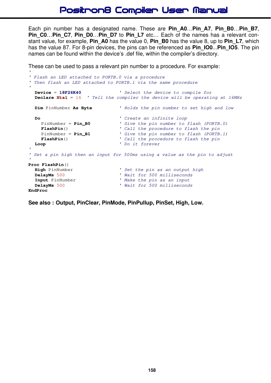
Input (PinInput)
Syntax
Input Port, Port.Pin or Pin Number
or
PinInput Port or Port.Pin or Pin Number
Overview
Makes the specified Port or Pin an input. Because the Input command is mostly used to alter a Port’s pin. The name PinInput can also be used instead of the name Input. They both work exactly the same but make the source code a little clearer to read and follow.
Parameters
Port must be the name of a Port. Port.Bit must be any valid port and bit combination, i.e. PORTA.1 Pin Number can be any variable or constant holding 0 to the amount of I/O pins on the device. A value of 0 will be PORTA.0, if present, 1 will be PORTA.1, 8 will be PORTB.0 etc…
Example 1
Input PORTA.0      ' Make pin-0 of PORTA an input
Input PORTA        ' Make all pins of PORTA inputs
Input 0            ' Make pin-0 of PORTA an input
Input 8            ' Make pin-0 of PORTB an input
PinInput PORTB.0   ' Make pin-0 of PORTB an input
Example 2
' Flash each of the pins on PORTA and PORTB
'
  Device = 18F26K40        ' Select the device to compile for
  Declare Xtal = 16  ' Tell the compiler the device will be operating at 16MHz

   Dim MyPin as Byte

   High PORTA
   High PORTB
   For MyPin = 0 to 15     ' Create a loop for the pin to flash
     Output MyPin            ' Set the pin as an output
     DelayMs 500             ' Delay so that it can be seen
     Input MyPin             ' Set the pin as an input
     DelayMs 500             ' Delay so that it can be seen
   Next
Notes
An Alternative method for making a particular pin an input is by directly modifying the appropriate TRIS register: -
TRISB.0 = 1 ' Set PORTB, bit-0 to an inputAll of the pins on a port may be set to inputs by setting the whole TRIS register at once: -
TRISB = 0b11111111 ' Set all of PORTB to inputsIn the above examples, setting a TRIS bit to 1 makes the pin an input, and conversely, setting the bit to 0 makes the pin an output.
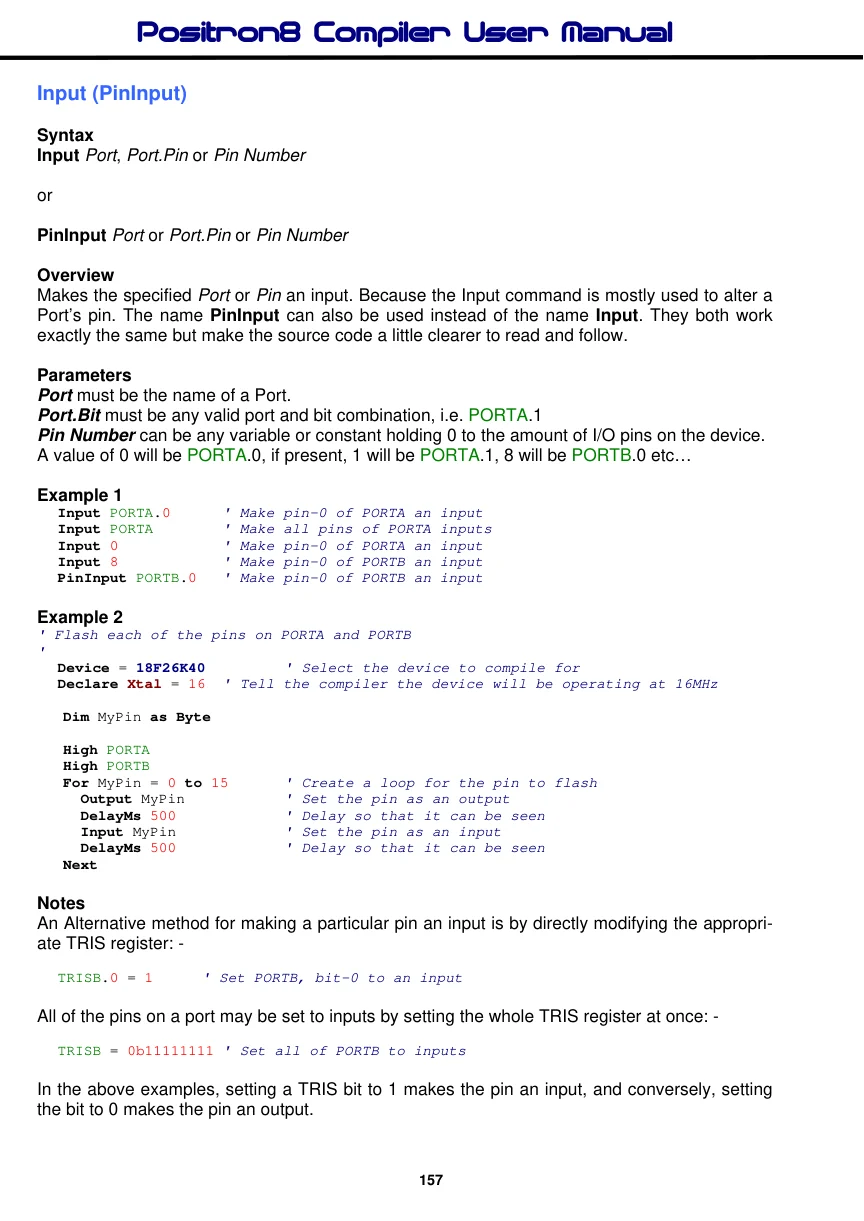
Each pin number has a designated name. These are Pin_A0…Pin_A7, Pin_B0…Pin_B7, Pin_C0…Pin_C7, Pin_D0…Pin_D7 to Pin_L7 etc… Each of the names has a relevant constant value, for example, Pin_A0 has the value 0, Pin_B0 has the value 8, up to Pin_L7, which has the value 87. For 8-pin devices, the pins can be referenced as Pin_IO0...Pin_IO5. The pin names can be found within the device’s .def file, within the compiler’s directory.
These can be used to pass a relevant pin number to a procedure. For example:
'
' Flash an LED attached to PORTB.0 via a procedure
' Then flash an LED attached to PORTB.1 via the same procedure
'
  Device = 18F26K40             ' Select the device to compile for
  Declare Xtal = 16  ' Tell the compiler the device will be operating at 16MHz

  Dim PinNumber As Byte          ' Holds the pin number to set high and low

  Do                             ' Create an infinite loop
     PinNumber = Pin_B0          ' Give the pin number to flash (PORTB.0)
     FlashPin()                  ' Call the procedure to flash the pin
     PinNumber = Pin_B1          ' Give the pin number to flash (PORTB.1)
     FlashPin()                  ' Call the procedure to flash the pin
  Loop                           ' Do it forever
'
' Set a pin high then an input for 500ms using a value as the pin to adjust
'
Proc FlashPin()
  High PinNumber                  ' Set the pin as an output high
  DelayMs 500                    ' Wait for 500 milliseconds
  Input PinNumber               ' Make the pin as an input
  DelayMs 500                    ' Wait for 500 milliseconds
EndProc
See also : Output, PinClear, PinMode, PinPullup, PinSet, High, Low.