USBin
Syntax
USBin Endpoint, Buffer, Countvar, Label
Overview
Receive USB data from the host computer and place it into Buffer.
Parameters
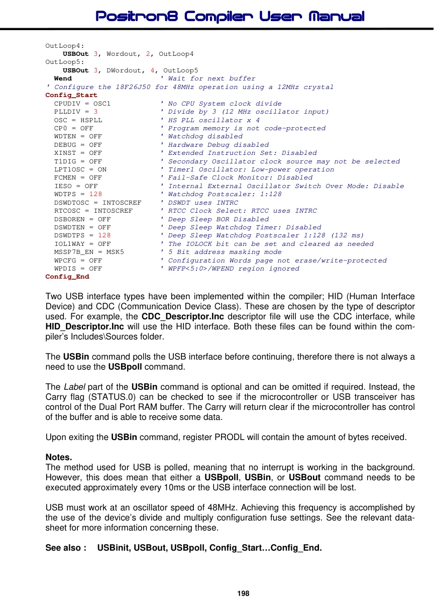
Endpoint is a constant value (0 - 15) that indicates which EndPoint to receive data from. Buffer is a Byte array or String that will contain the bytes received. This may be up to 128 bytes in length if using CDC and 64 bytes for HID. Countvar is a constant, variable or expression that indicates how many bytes are transferred from the Buffer. The text Auto may be placed instead of the Countvar parameter. This will configure the receiving bus to it’s maximum, which is 128 bytes for CDC and 64 bytes for HID. Label is an optional valid BASIC label, that USBin will jump to in the event that no data is available.
Example 1
' USB interface
  Dim Buffer[8] as Byte
Try_Again:
  USBin 1, Buffer, 4, Try_Again
Example 2
' USB demo program for CDC virtual serial emulation
' Wait for a byte from USB and transmit several characters
'
  Declare Reminders = Off
  Device = 18F26J50
  Declare Xtal = 48  ' Tell the compiler the device will be operating at 48MHz

  Include "CDC_Descriptor.inc"             ' Include the CDC descriptors

  Dim Byteout As Byte = $41
  Dim Wordout As Word = $4142
  Dim DWordout As Dword = $41424344
  Dim RxBuffer[16] As Byte
  Dim TxBuffer As String * 16 = "Hello World\r"
  Dim CodeText As Code = "Hello World\r"

  OSCTUNE.6 = 1                            ' Enable PLL for 18F87J50 family
  DelayMs 10
  USBInit                                  ' Initialise USB

  While
IdleLoop:
    USBIn 3, RxBuffer, 16, IdleLoop        ' Wait for USB input
' Transmit to a serial terminal
OutLoop1:
    USBOut 3, CodeText, Auto, OutLoop1
OutLoop2:
    USBOut 3, TxBuffer, Auto, OutLoop2
OutLoop3:
    USBOut 3, Byteout, 1, OutLoop3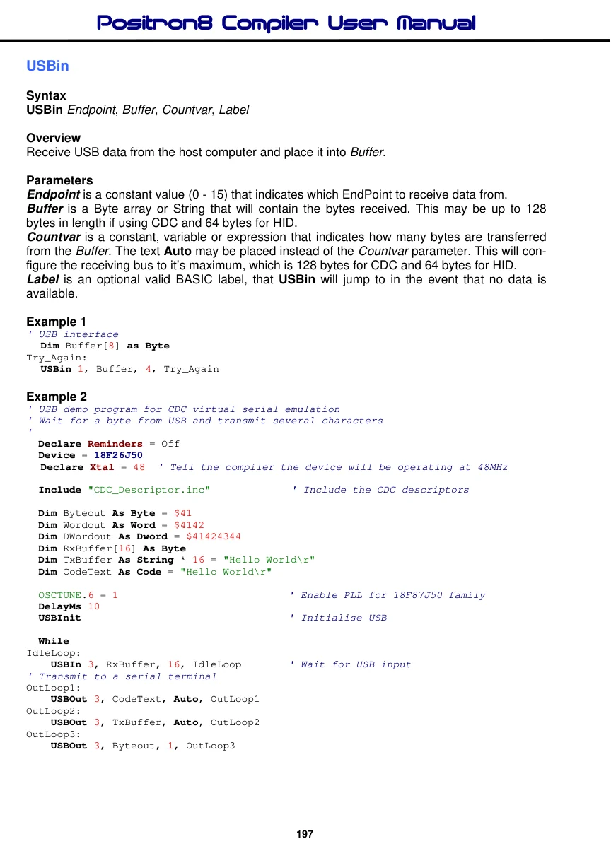
OutLoop4:
    USBOut 3, Wordout, 2, OutLoop4
OutLoop5:
    USBOut 3, DWordout, 4, OutLoop5
  Wend                    ' Wait for next buffer
' Configure the 18F26J50 for 48MHz operation using a 12MHz crystal
Config_Start
  CPUDIV = OSC1          ' No CPU System clock divide
  PLLDIV = 3             ' Divide by 3 (12 MHz oscillator input)
  OSC = HSPLL             ' HS PLL oscillator x 4
  CP0 = OFF              ' Program memory is not code-protected
  WDTEN = OFF             ' Watchdog disabled
  DEBUG = OFF             ' Hardware Debug disabled
  XINST = OFF             ' Extended Instruction Set: Disabled
  T1DIG = OFF             ' Secondary Oscillator clock source may not be selected
  LPT1OSC = ON           ' Timer1 Oscillator: Low-power operation
  FCMEN = OFF             ' Fail-Safe Clock Monitor: Disabled
  IESO = OFF              ' Internal External Oscillator Switch Over Mode: Disable
  WDTPS = 128             ' Watchdog Postscaler: 1:128
  DSWDTOSC = INTOSCREF    ' DSWDT uses INTRC
  RTCOSC = INTOSCREF     ' RTCC Clock Select: RTCC uses INTRC
  DSBOREN = OFF          ' Deep Sleep BOR Disabled
  DSWDTEN = OFF          ' Deep Sleep Watchdog Timer: Disabled
  DSWDTPS = 128          ' Deep Sleep Watchdog Postscaler 1:128 (132 ms)
  IOL1WAY = OFF          ' The IOLOCK bit can be set and cleared as needed
  MSSP7B_EN = MSK5        ' 5 Bit address masking mode
  WPCFG = OFF            ' Configuration Words page not erase/write-protected
  WPDIS = OFF             ' WPFP<5:0>/WPEND region ignored
Config_End
Two USB interface types have been implemented within the compiler; HID (Human Interface Device) and CDC (Communication Device Class). These are chosen by the type of descriptor used. For example, the CDC_Descriptor.Inc descriptor file will use the CDC interface, while HID_Descriptor.Inc will use the HID interface. Both these files can be found within the compiler’s Includes\Sources folder.
The USBin command polls the USB interface before continuing, therefore there is not always a need to use the USBpoll command.
The Label part of the USBin command is optional and can be omitted if required. Instead, the Carry flag (STATUS.0) can be checked to see if the microcontroller or USB transceiver has control of the Dual Port RAM buffer. The Carry will return clear if the microcontroller has control of the buffer and is able to receive some data.
Upon exiting the USBin command, register PRODL will contain the amount of bytes received.
Notes.
The method used for USB is polled, meaning that no interrupt is working in the background. However, this does mean that either a USBpoll, USBin, or USBout command needs to be executed approximately every 10ms or the USB interface connection will be lost.
USB must work at an oscillator speed of 48MHz. Achieving this frequency is accomplished by the use of the device’s divide and multiply configuration fuse settings. See the relevant datasheet for more information concerning these.
See also : USBinit, USBout, USBpoll, Config_Start…Config_End.