USBout
Syntax
USBout Endpoint, Buffer, Countvar, Label
Overview
Take Countvar number of bytes from Buffer and send them to the USB Endpoint.
Parameters
Endpoint is a constant value (0 - 15) that indicates which EndPoint to transmit data from. Buffer can be any of the compiler's variable or constant types, and contains the bytes to transmit. This may be up to 128 bytes in length if using CDC and 64 bytes for HID. Countvar is a constant, variable or expression that indicates how many bytes are transferred from the Buffer. The text Auto may be placed instead of the Countvar value, which will transmit data until a null is found, or until the correct amount of bytes are transmitted for the variable size. Label is an optional valid BASIC label, that USBout will jump to in the event that no data is available.
Example
  Dim Buffer[8] as Byte
Try_Again:
  USBout 1, Buffer, 4, Try_Again
Notes. The Label used for buffer control may be omitted and the microcontroller’s Carry flag (STATUS.0) monitored instead:-
Repeat
  USBout 3, USB_BUFFER, 4   ' Transmit 4 bytes from USB_BUFFER
Until STATUS.0 = 0          ' Wait for control over the buffer RAM
The CountVar parameter can also be replaced with the text Auto, in which case a string of characters terminated by a null (0) will be transmitted, or the amount of bytes that a particular variable type used will be transmitted. The Countvar parameter can be omitted, in which case Auto is implied: -
USBout 3, "Hello Wordl\n\r"The buffer itself can take the form of any variable type of the compiler, and even the internal USB buffer itself. The internal USB buffer is brought into the BASIC code named __USBout_Buffer (note the two preceding underscores).
In the event that Auto has been used for the Countvar parameter, a Bit or Byte variable will transmit 1 byte of data, a Word will transmit 2 bytes (lowest byte first), a Dword and Float will transmit 4 bytes of data (lowest byte first).
The method used for USB is polled, meaning that no interrupt is working in the background. However, this does mean that either a USBpoll, USBin, or USBout command needs to be executed approximately every 10ms for HID and 5ms for CDC or the USB interface connection will be lost.
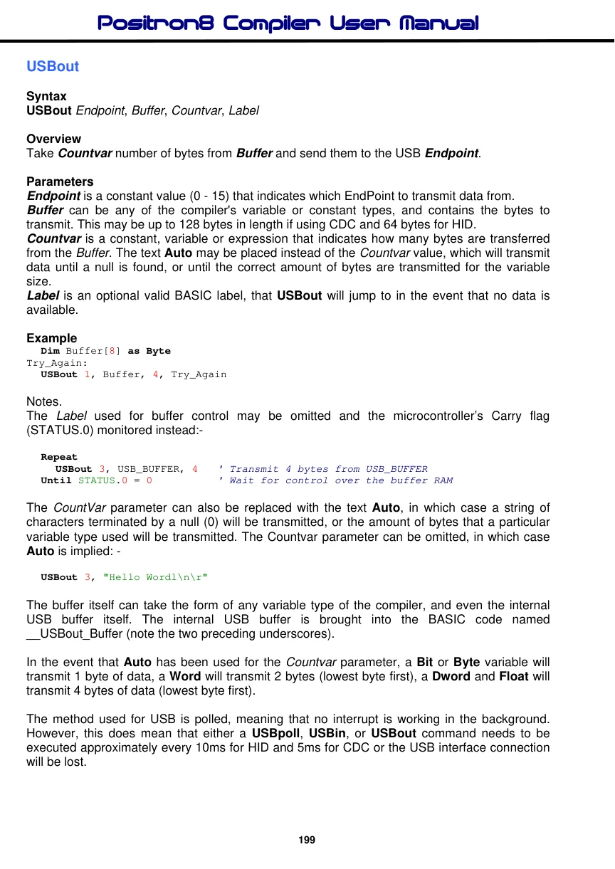
The USB library subroutines require the use of the DP (Dual Port) RAM starting at address $0200 or $0400 depending on the device used. This leaves the RAM underneath DP RAM available for the BASIC program. However, the DP USB buffers can also be accessed directly from BASIC. __USBOUT_BUFFER, and __USBIN_BUFFER are declared automatically as String type variables within the USB_Mem.inc file, located within the compiler Includes\Sources folder.
USB must work at an oscillator speed of 48MHz. Achieving this frequency is accomplished by the use of the device’s divide and multiply configuration fuse settings. See the relevant datasheet for more information concerning these.

Text in this figure or table
1 MCLR 11 VDD
32 C1
VDD
100nF Disconnect
12 USB Cable's +5V line VSS if externally powered. 31 VSS
PIC18F4550 C2 * USB Cable to 220nF
| 18 | Computer |
| Vusb | +5V |
GND D-
23 D+
D-
24 D+
C3 15pF
13 *C2 must always be fitted. OSC1 Without it the USB connection will be erratic. 20MHz Crystal
C4 15pF
14 OSC2
Typical circuit for self powered USB interface.
The USBout command polls the USB interface before transferring its data to the bus, and returns with the Carry flag (STATUS.0) clear if it has control over the Dual Port buffer.
Repeat
  USBout 3, __USBout_BUFFER, Auto
Until STATUS.0 = 0
Two USB interface types have been implemented within the compiler; HID (Human Interface Device) and CDC (Communication Device Class). These are chosen by the type of descriptor used. For example, the CDC_Descriptor.Inc descriptor file will use the CDC interface, while HID_Descriptor.Inc will use the HID interface. Both these files can be found within the compiler’s Includes\Sources folder.
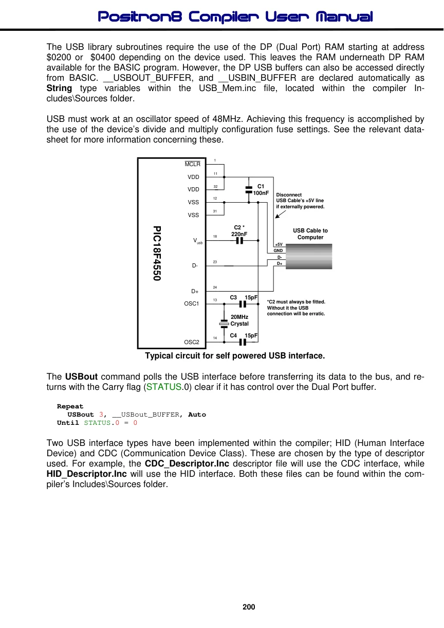
Example.
' Demonstrate a HID (Human Interface Device) interface
' When connected to the PC, the mouse pointer will rotate in a small square

  Device = 18F4550               ' Choose a device with on-board full speed USB
  Declare Xtal = 48              ' Inform the compiler we’re operating at 48MHz

  Include "HID_Descriptor.inc"   ' Include the HID descriptors

  Dim Buffer[4] As Byte
  Dim Loop_Count As Byte
  Dim Position As Byte

'------------------------------------------------------------------------
' The main program loop starts here
  DelayMs 10                        ' Wait for things to stabilise
  Clear Buffer                     ' Clear the array before we start

  Repeat
    USBPoll                        '   Wait for USB to become attached
  Until USB_tConnected = 1 Or USB_tConfigured = 1
    Do
      For Position = 0 To 3         ' Move through each position
        For Loop_Count = 0 To 31   ' 32 steps in each direction
          Select Position
            Case 0                  ' Move Up?
              Buffer#1 = 0
              Buffer#2 = -2
            Case 1                  ' Move Right?
              Buffer#1 = 2
              Buffer#2 = 0
            Case 2                  ' Move Down?
              Buffer#1 = 0
              Buffer#2 = 2
            Case 3                  ' Move Left?
              Buffer#1 = -2
              Buffer#2 = 0
           EndSelect
           Repeat
             USBOut 1, Buffer, 4   ' Send the Buffer to endpoint 1
           Until STATUSbits_C = 0   ' Keep trying if we don’t have control
        Next
      Next
    Loop
'------------------------------------------------------------------------
' Configure the 18F4550 for 48MHz operation using a 12MHz crystal
Config_Start
  PLLDIV = 3           ' Divide by 3 (12 MHz oscillator input)
  CPUDIV = OSC1_PLL2   ' [OSC1/OSC2 Src: /1][96 MHz PLL Src: /2]
  USBDIV = 1          ' USB clock source comes directly from the primary osc
  FOSC = HSPLL_HS      ' HS oscillator, PLL enabled
  FCMEN = OFF           ' Fail-Safe Clock Monitor disabled
  IESO = OFF           ' Oscillator Switchover mode disabled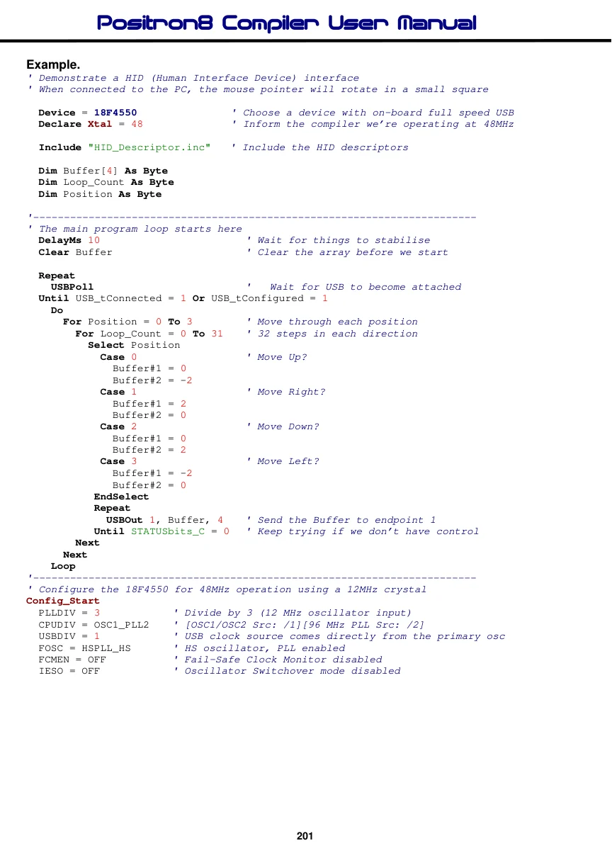
  PWRT = ON      ' PWRT enabled
  BOR = ON       ' Brown-out Reset enabled in hardware only
  BORV = 3       ' Brown-out Voltage bits: Minimum setting
  VREGEN = ON    ' USB voltage regulator enabled
  WDT = OFF      ' Watchdog Timer  Disabled - SW Controlled
  WDTPS = 128    ' Watchdog Timer Postscale Select bits: 1:128
  MCLRE = ON     ' MCLR pin enabled, RE3 input pin disabled
  LPT1OSC = ON   ' Timer1 configured for low-power operation
  PBADEN = OFF   ' PORTB<4:0> pins are configured as digital I/O on Reset
  CCP2MX = ON    ' CCP2 input/output is multiplexed with RC1
  STVREN = OFF   ' Stack full/underflow will not cause Reset
  LVP = OFF      ' Single-Supply ICSP disabled
  XINST = OFF    ' Instruction set extension disabled
  DEBUG = OFF    ' Background debugger disabled
  CP0 = OFF      ' Block 0 (000800-001FFFh) not code-protected
  CP1 = OFF      ' Block 1 (002000-003FFFh) not code-protected
  CP2 = OFF      ' Block 2 (004000-005FFFh) not code-protected
  CP3 = OFF      ' Block 3 (006000-007FFFh) not code-protected
  CPB = OFF      ' Boot block (000000-0007FFh) not code-protected
  CPD = OFF      ' Data EEPROM not code-protected
  WRT0 = OFF     ' Block 0 (000800-001FFFh) not write-protected
  WRT1 = OFF     ' Block 1 (002000-003FFFh) not write-protected
  WRT2 = OFF     ' Block 2 (004000-005FFFh) not write-protected
  WRT3 = OFF     ' Block 3 (006000-007FFFh) not write-protected
  WRTB = OFF     ' Boot block (000000-0007FFh) not write-protected
  WRTC = OFF     ' Config registers (300000-3000FFh) not write-protected
  WRTD = OFF     ' Data EEPROM not write-protected
  EBTR0 = OFF    ' Block 0 not protected from table reads
  EBTR1 = OFF    ' Block 1 not protected
  EBTR2 = OFF    ' Block 2 not protected
  EBTR3 = OFF    ' Block 3 not protected
  EBTRB = OFF    ' Boot block not protected
Config_End
See also : USBinit, USBin, USBpoll, Config_Start…Config_End.