Oread
Syntax
Oread DQ_Pin, Mode, [ InputData ]
Overview
Receive data from a device using the Dallas Semiconductor 1-wire protocol. The 1-wire protocol is a form of asynchronous serial communication developed by Dallas Semiconductor. It requires only one I/O pin which may be shared between multiple 1-wire devices.
Parameters
DQ_Pin is a Port-Bit combination that specifies which I/O pin to use. 1-wire devices require only one I/O pin (normally called DQ) to communicate. This I/O pin will be toggled between output and input mode during the Oread command and will be set to input mode at the end of the Oread command. Mode is a numeric constant (0 - 7) indicating the mode of data transfer. The Mode parameter controls the placement of reset pulses and detection of presence pulses, as well as byte or bit input. See notes below. InputData is a list of variables or arrays to store the incoming data into.
Example
Dim bMyResult as Byte
Symbol DQ_Pin = PORTA.0

Oread DQ_Pin, 1, [bMyResult]
The above example code will transmit a 'reset' pulse to a 1-wire device (connected to bit-0 of PORTA) and will then detect the device's 'presence' pulse and receive one byte and store it in the variable bMyResult.
Notes
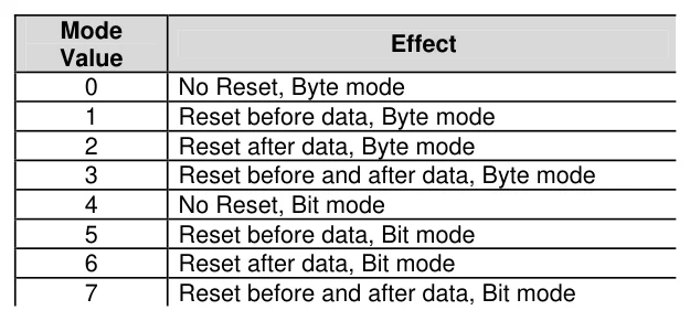
The Mode parameter is used to control placement of reset pulses (and detection of presence pulses) and to designate byte or bit input. The table below shows the meaning of each of the 8 possible value combinations for Mode.
Text in this figure or table
Mode Effect Value
| 0 | No Reset, Byte mode |
| 1 | Reset before data, Byte mode |
| 2 | Reset after data, Byte mode |
| 3 | Reset before and after data, Byte mode |
| 4 | No Reset, Bit mode |
| 5 | Reset before data, Bit mode |
| 6 | Reset after data, Bit mode |
| 7 | Reset before and after data, Bit mode |
The correct value for Mode depends on the 1-wire device and the portion of the communication that is being dealt with. Consult the data sheet for the device in question to determine the correct value for Mode. In many cases, however, when using the Oread command, Mode should be set for either No Reset (to receive data from a transaction already started by an Owrite
command) or a Reset after data (to terminate the session after data is received). However, this may vary due to device and application requirements.
When using the Bit (rather than Byte) mode of data transfer, all variables in the InputData argument will only receive one bit. For example, the following code could be used to receive two bits using this mode: -
Dim tBitVar1 as Bit
Dim tBitVar2 as Bit
Oread PORTA.0, 6, [tBitVar1, tBitVar2]
In the example code shown, a value of 6 was chosen for Mode. This sets Bit transfer and Reset after data mode.
We could also have chosen to make the tBitVar1 and tBitVar2 variables each a Byte type, however, they would still only have received one bit each in the Oread command, due to the Mode that was chosen.
The compiler also has a modifier for handling a string of data, named Str.
The Str modifier is used for receiving data and placing it directly into a byte array variable.
A string is a set of bytes that are arranged or accessed in a certain order. The values 1, 2, 3 would be stored in a string with the value 1 first, followed by 2 then followed by the value 3. A byte array is a similar concept to a string; it contains data that is arranged in a certain order. Each of the elements in an array is the same size. The string 1 2 3 would be stored in a byte array containing three bytes (elements).
Below is an example that receives ten bytes through a 1-wire interface and stores them in the 10 element byte array, MyArray: -
Dim bMyArray[10] as Byte       ' Create a 10 element byte array.
Oread DQ_Pin, 1, [Str bMyArray]
Print Dec Str bMyArray        ' Display the values.
If the amount of received characters is not enough to fill the entire array, then a formatter may be placed after the array's name, which will only receive characters until the specified length is reached. For example: -
Dim bMyArray[10] as Byte         ' Create a 10 element byte array.
Oread DQ_Pin, 1, [Str bMyArray\5] ' Fill the first 5-bytes of array with data.
Print Str bMyArray \5           ' Display the 5-value string.
The example above illustrates how to fill only the first n bytes of an array, and then how to display only the first n bytes of the array. n refers to the value placed after the backslash.
Dallas 1-Wire Protocol.
The 1-wire protocol has a well defined standard for transaction sequences. Every transaction sequence consists of four parts: -
Initialisation. ROM Function Command. Memory Function Command. Transaction / Data.
Additionally, the ROM Function Command and Memory Function Command are always 8 bits wide and are sent least-significant-bit first (LSB).
The Initialisation consists of a reset pulse (generated by the master) that is followed by a presence pulse (generated by all slave devices).
The reset pulse is controlled by the lowest two bits of the Mode argument in the Oread command. It can be made to appear before the ROM Function Command (Mode = 1), after the Transaction / Data portion (Mode = 2), before and after the entire transaction (Mode = 3) or not at all (Mode = 0).
Text in this figure or table
Command Value Action
Reads the 64-bit ID of the 1-wire device. This command can
Read ROM $33
only be used if there is a single 1-wire device on the line. This command, followed by a 64-bit ID, allows the PICmicro to
Match ROM $55
address a specific 1-wire device. Address a 1-wire device without its 64-bit ID. This command
Skip ROM $CC
can only be used if there is a single 1-wire device on the line. Reads the 64-bit IDs of all the 1-wire devices on the line. A Search
$F0 process of elimination is used to distinguish each unique de-
ROM vice.
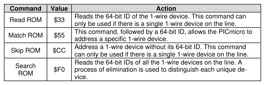
Following the Initialisation, comes the ROM Function Command. The ROM Function Command is used to address the desired 1-wire device. The above table shows a few common ROM Function Commands. If only a single 1 wire device is connected, the Match ROM command can be used to address it. If more than one 1-wire device is attached, the PICmicro™ will ultimately have to address them individually using the Match ROM command.
The third part, the Memory Function Command, allows the PICmicro™ to address specific memory locations, or features, of the 1-wire device. Refer to the 1-wire device's data sheet for a list of the available Memory Function Commands.
Text in this figure or table
DS1820 +5 Volts 3 VDD 4.7k DS1820 2
1 2 3 1..GND 0v 3..VCC
Finally, the Transaction / Data section is used to read or write
data to the 1-wire device. The Oread command will read data R1
at this point in the transaction. A read is accomplished by
| generating a brief low-pulse and sampling the line within | To RA1 | DQ |
| 15us of the falling edge of the pulse. This is called a 'Read | GND | |
| Slot'. | 1 | 2..DQ |
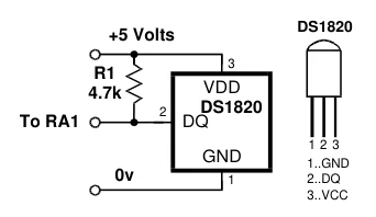
The following program demonstrates interfacing to a Dallas Semiconductor DS1820 1-wire digital thermometer device using the compiler's 1-wire commands, and connections as per the diagram to the right.
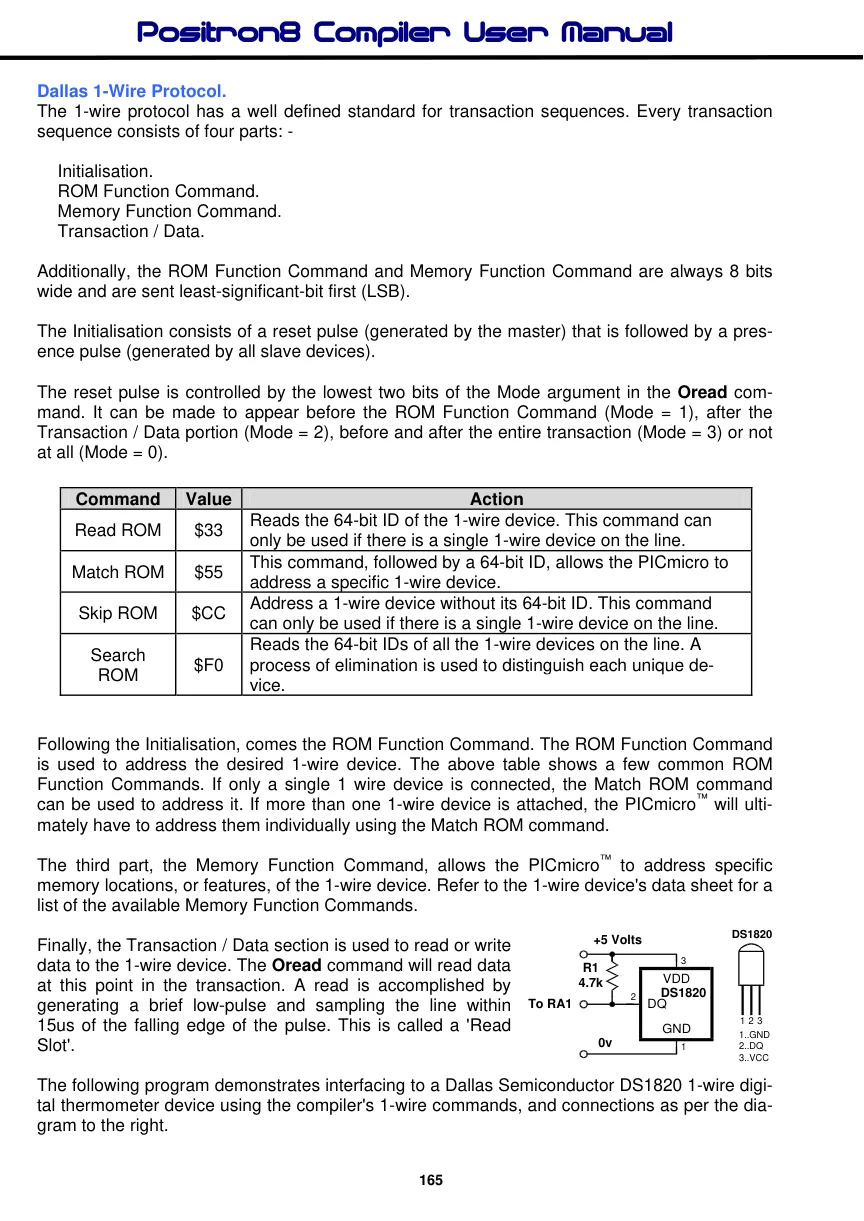
The code reads the Counts Remaining and Counts per Degree Centigrade registers within the DS1820 device in order to provide a more accurate temperature (down to 1/10th of a degree).
Device = 18F26K40             ' Select the device to compile for
Declare Xtal = 16  ' Tell the compiler the device will be operating at 16MHz
Declare Hserial_Baud = 9600  ' Set the Baud rate for HRsoutLn

Symbol DQ_Pin = PORTA.1          ' Place the DS1820 on bit-1 of PORTA
Dim wTemperature as Word         ' Holds the temperature value
Dim bCounts as Byte              ' Holds the counts remaining value
Dim bCPerD as Byte              ' Holds the Counts per degree C value

Do
  Owrite DQ_Pin, 1, [$CC, $44]   ' Send a Calculate Temperature command
  Repeat
     DelayMs 25                  ' Wait until conversion is complete
     Oread DQ_Pin, 4, [bCounts]   ' Keep reading low pulses until
  Until bCounts <> 0             ' the DS1820 is finished.
  Owrite DQ_Pin, 1, [$CC, $BE]   ' Send a Read ScratchPad command
  Oread DQ_Pin, 2,[wTemperature.LowByte, wTemperature.HighByte,_
                    bCounts, bCounts, bCounts, bCounts, bCounts,_
                    CPerD]
  '
  ' Calculate the temperature in degrees Centigrade
  '
  wTemp = (((wTemperature >> 1)*100) - 25) + (((bCPerD - bCounts)*100) / bCPerD)
  HRsoutLn Dec wTemperature / 100, ".", Dec2 wTemperature, " C"
  DelayMs 500
Loop
Note. The simple expression used in the example above will not work correctly with negative temperatures. Also note that a 4.7kΩ pull-up resistor (R1) is required for correct operation.
Inline Oread Command.
The standard structure of the Oread command is: -
Oread DQ_Pin, Mode, [ InputData ]
However, this did not allow it to be used in conditions such as If-Then, While-Wend etc. Therefore, there is now an additional structure to the Oread command: -
Var = Oread DQ_Pin, Mode
Parameters DQ_Pin and Mode have not changed their function, but the result from the 1-wire read is now placed directly into the assignment variable.
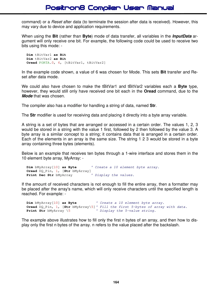
Oread - Owrite Presence Detection.
Another important feature to both the Oread and Owrite commands is the ability to jump to a section of the program if a presence is not detected on the 1-wire bus.
Owrite DQ_Pin, Mode, Label, [ OutputData ]
Oread DQ_Pin, Mode, Label, [ InputData ]
Var = Oread DQ_Pin, Mode, Label
The Label parameter is an optional condition, but if used, it must reference a valid BASIC label.
' Skip ROM search & do temp conversion
'
  Owrite DQ_Pin, 1, NoPresence, [$CC, $44]
  While Oread DQ_Pin, 4, NoPresence <> 0 : Wend ' Read busy-bit,' Still busy..?
'
' Skip ROM search & read scratchpad memory
'
  Owrite DQ_Pin, 1, NoPresence, [$CC, $BE]
  Oread  DQ_Pin, 2, NoPresence, [wTemp.Lowbyte, wTemp.Highbyte] ' Read two bytes
  Return

NoPresence:
  HRsoutLn "No Presence"
  Stop
See also : Owrite.