Serout
Syntax
Serout Tpin { \ Fpin }, Baudmode, { Pace, } { Timeout, Tlabel, } [ OutputData ]
Overview
Transmit asynchronous serial data (i.e. RS232 data).
Parameters
Tpin is a Port.Bit constant that specifies the I/O pin through which the serial data will be transmitted. This pin will be set to output mode while operating. The state of this pin when finished is determined by the driver bit in Baudmode. Fpin is an optional Port.Bit constant that specifies the I/O pin to monitor for flow control status. This pin will be set to input mode. Note: Fpin must be specified in order to use the optional Timeout and Tlabel operators in the Serout command. Baudmode may be a variable, constant, or expression (0 - 65535) that specifies serial timing and configuration. Pace is an optional variable, constant, or expression (0 - 65535) that determines the length of the delay between transmitted bytes. Note: Pace cannot be used simultaneously with Timeout. Timeout is an optional variable or constant (0 - 65535) that informs Serout how long to wait for Fpin permission to send. If permission does not arrive in time, the program will jump to the address specified by Tlabel. Note: Fpin must be specified in order to use the optional Timeout and Tlabel operators in the Serout command. Tlabel is an optional label that must be provided along with Timeout. Tlabel indicates where the program should jump to in the event that permission to send data is not granted within the period specified by Timeout. OutputData is list of variables, constants, expressions and modifiers that informs Serout how to format outgoing data. Serout can transmit individual or repeating bytes, convert values into decimal, hex or binary text representations, or transmit strings of bytes from variable arrays, and Cdata constructs. These actions can be combined in any order in the OutputData list.
Notes
One of the most popular forms of communication between electronic devices is serial communication. There are two major types of serial communication; asynchronous and synchronous. The Rsin, Rsout, Serin and Serout commands are all used to send and receive asynchronous serial data. While the Shin and Shout commands are for use with synchronous communications.
The term asynchronous means ‘no clock.' More specifically, ‘asynchronous serial communication' means data is transmitted and received without the use of a separate ‘clock' line. Data can be sent using as few as two wires; one for data and one for ground. The PC's serial ports (also called COM ports or RS232 ports) use asynchronous serial communication. Note: the other kind of serial communication, synchronous, uses at least three wires; one for clock, one for data and one for ground.
RS232 is the electrical specification for the signals that PC serial ports use. Unlike standard TTL logic, where 5 volts is a logic 1 and 0 volts is logic 0, RS232 uses -12 volts for logic 1 and +12 volts for logic 0. This specification allows communication over longer wire lengths without amplification.
Most circuits that work with RS232 use a line driver / receiver (transceiver). This component does two things: -
Convert the ±12 volts of RS-232 to TTL compatible 0 to 5 volt levels. Invert the voltage levels, so that 5 volts = logic 1 and 0 volts = logic 0.
By far, the most common line driver device is the MAX232 from MAXIM semiconductor. With the addition of a few capacitors, a complete 2-way level converter is realised (see Serin for circuit).
The MAX232 is not the only device available, there are other types that do not require any ex-
ternal capacitors at all. Visit Maxim's excellent web site at www.maxim.com
<http://www.maxim.com>, and download one of their many detailed datasheets.
Because of the excellent IO capabilities of the PICmicro™ range of devices, and the adoption of TTL levels on most modern PC serial ports, a line driver is often unnecessary unless long distances are involved between the transmitter and the receiver. Instead a simple current limiting resistor is all that's required (see Serin for circuit).
You should remember that when using a line transceiver such as the MAX232, the serial mode (polarity) is inverted in the process of converting the signal levels, however, if using the direct connection, the mode is untouched. This is the single most common cause of errors when connecting serial devices, therefore you must make allowances for this within your software.
Asynchronous serial communication relies on precise timing. Both the sender and receiver must be set for identical timing, this is commonly expressed in bits per second (bps) called Baud. Serout requires a value called Baudmode that informs it of the relevant characteristics of the incoming serial data; the bit period, number of data and parity bits, and polarity.
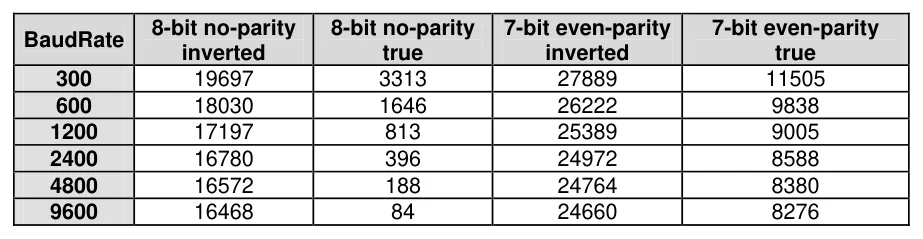
The Baudmode argument for Serout accepts a 16-bit value that determines its characteristics: 1-stop bit, 8-data bits/no-parity or 7-data bits/even-parity and virtually any speed from as low as 300 Baud to 38400 Baud (depending on the crystal frequency used). Table 2 below shows how Baudmode is calculated, while table 3 shows some common Baudmodes for standard serial Baud rates.

Text in this figure or table
| Step 1. | Determine the bit period. (bits 0 – 11) | (1,000,000 / Baud rate) – 20 |
| Step 2. | 8-bit/no-parity = step 1 + 0 |
data bits and parity. (bit 13) 7-bit/even-parity = step 1 + 8192
Step 3. True (non-inverted) = step 2 + 0
Select polarity. (bit 14) Inverted = step 2 + 16384 Baudmode calculation.
Add the results of steps 1, 2 3, and 3 to determine the correct value for the Baudmode parameter
Text in this figure or table
8-bit no-parity 8-bit no-parity 7-bit even-parity 7-bit even-parity
BaudRate
| inverted | true | inverted | true | |
| 300 | 19697 | 3313 | 27889 | 11505 |
| 600 | 18030 | 1646 | 26222 | 9838 |
| 1200 | 17197 | 813 | 25389 | 9005 |
| 2400 | 16780 | 396 | 24972 | 8588 |
| 4800 | 16572 | 188 | 24764 | 8380 |
| 9600 | 16468 | 84 | 24660 | 8276 |

Note
For 'open' Baudmodes used in networking, add 32768 to the values from the previous table.
If communications are with existing software or hardware, its speed and mode will determine the choice of Baud rate and mode. In general, 7-bit/even-parity (7E) mode is used for text, and 8-bit/no-parity (8N) for byte-oriented data. Note: the most common mode is 8-bit/no-parity, even when the data transmitted is just text. Most devices that use a 7-bit data mode do so in order to take advantage of the parity feature. Parity can detect some communication errors, but to use it you lose one data bit. This means that incoming data bytes transferred in 7E (even-parity) mode can only represent values from 0 to 127, rather than the 0 to 255 of 8N (no-parity) mode.
The compiler's serial commands Serout and Serin, have the option of still using a parity bit with 4 to 8 data bits. This is through the use of a Declare: -
With parity disabled (the default setting): -
Declare Serial_Data 4   ' Set Serout and Serin data bits to 4
Declare Serial_Data 5   ' Set Serout and Serin data bits to 5
Declare Serial_Data 6   ' Set Serout and Serin data bits to 6
Declare Serial_Data 7   ' Set Serout and Serin data bits to 7
Declare Serial_Data 8   ' Set Serout and Serin data bits to 8 (default)
With parity enabled: -
Declare Serial_Data 5   ' Set Serout and Serin data bits to 4
Declare Serial_Data 6   ' Set Serout and Serin data bits to 5
Declare Serial_Data 7   ' Set Serout and Serin data bits to 6
Declare Serial_Data 8   ' Set Serout and Serin data bits to 7 (default)
Declare Serial_Data 9   ' Set Serout and Serin data bits to 8
Serial_Data data bits may range from 4 bits to 8 (the default if no Declare is issued). Enabling parity uses one of the number of bits specified.
Declaring Serial_Data as 9 allows 8 bits to be read and written along with a 9th parity bit.
Parity is a simple error-checking feature. When the Serout command's Baudmode is set for even parity (compiler default) it counts the number of 1s in the outgoing byte and uses the parity bit to make that number even. For example, if it is sending the 7-bit value: 0b0011010, it sets the parity bit to 1 in order to make an even number of 1s (four).
The receiver also counts the data bits to calculate what the parity bit should be. If it matches the parity bit received, the serial receiver assumes that the data was received correctly. Of course, this is not necessarily true, since two incorrectly received bits could make parity seem correct when the data was wrong, or the parity bit itself could be bad when the rest of the data was correct. Parity errors are only detected on the receiver side.
Normally, the receiver determines how to handle an error. In a more robust application, the receiver and transmitter might be set up in such that the receiver can request a re-send of data that was received with a parity error.

Serout Modifiers.
The example below will transmit a single byte from bit-0 of PORTA at 2400 Baud, 8N1, inverted: -
Serout PORTA.0, 16780, [65]In the above example, Serout will transmit a byte equal to 65 (the ASCII value of the character "A" ) through PORTA.0. If the PICmicro™ was connected to a PC running a terminal program such as HyperTerminal set to the same Baud rate, the character "A" would appear on the screen. Always remembering that the polarity will differ if a line transceiver such as the MAX232 is used.
What if you wanted the value 65 to appear on the PC's screen? As was stated earlier, it is up to the receiving side (in serial communication) to interpret the values. In this case, the PC is interpreting the byte-sized value to be the ASCII code for the character "A". Unless you're also writing the software for the PC, you cannot change how the PC interprets the incoming serial data, therefore to solve this problem, the data needs to be translated before it is sent.
The Serout command provides a modifier which will translate the value 65 into two ASCII codes for the characters "6" and "5" and then transmit them: -
Serout PORTA.0, 16780, [Dec 65]Notice that the decimal modifier in the Serout command is the word Dec. This modifier informs the Serout command to convert the number into separate ASCII characters which represent the value in decimal form. If the value 65 in the code were changed to 123, the Serout command would send three bytes (49, 50 and 51) corresponding to the characters "1", "2" and "3".
This is exactly the same modifier that is used in the Rsout and Print commands.
As well as the Dec modifier, Serout may use Hex, or Bin modifiers, again, these are the same as used in the Rsout and Print commands. Therefore, please refer to the Rsout or Print command descriptions for an explanation of these. The Serout command sends quoted text exactly as it appears in the OutputData list:
Serout PORTA.0, 16780, ["Hello World", 13]
Serout PORTA.0, 16780, ["Num = ", Dec 100]
The above code will display "Hello World" on one line and "Num = 100" on the next line. Notice that you can combine data to output in one Serout command, separated by commas. In the example above, we could have written it as one line of code: -
Serout PORTA.0, 16780, ["Hello World", 13, "Num = ", Dec 100]
Serout also has some other modifiers. These are listed below: -
Modifier Operation
At ypos,xpos Position the cursor on a serial LCD
| Cls | Clear a serial LCD (also creates a 30ms delay) |
| Bin{1..32} | Send binary digits |
| Dec{0..10} | Send decimal digits (amount of digits after decimal point with floating point) |
| Hex{1..8} | Send hexadecimal digits |
| Sbin{1..32} | Send signed binary digits |
| Sdec{0..10} | Send signed decimal digits |
| Shex{1..8} | Send signed hexadecimal digits |
| Ibin{1..32} | Send binary digits with a preceding '%' identifier |
| Idec{0..10} | Send decimal digits with a preceding '#' identifier |
| Ihex{1..8} | Send hexadecimal digits with a preceding '$' identifier |
| ISbin{1..32} | Send signed binary digits with a preceding '%' identifier |
| ISdec{0..10} | Send signed decimal digits with a preceding '#' identifier |
| IShex{1..8} | Send signed hexadecimal digits with a preceding '$' identifier |
| Rep c\n | Send character c repeated n times |
If a floating point variable is to be displayed, then the digits after the Dec modifier determine how many remainder digits are printed. i.e. numbers after the decimal point.
Dim MyFloat as Float
MyFloat = 3.145
Serout PORTA.0, 16780, [Dec2 MyFloat]' Send 2 values after decimal point
The above program will send 3.14
If the digit after the Dec modifier is omitted, then 3 values will be displayed after the decimal point.
Dim MyFloat as Float
MyFloat = 3.1456
Serout PORTA.0, 16780, [Dec MyFloat]   ' Send 3 values after decimal point
The above program will send 3.145
There is no need to use the Sdec modifier for signed floating point values, as the compiler's Dec modifier will automatically display a minus result: -
Dim MyFloat as Float
MyFloat = -3.1456
Serout PORTA.0, 16780, [Dec MyFloat]   ' Send 3 values after decimal point
The above program will send -3.145
Hex or Bin modifiers cannot be used with floating point values or variables.

Using Strings with Serout.
The Str modifier is used for transmitting a string of characters from a byte array variable. A string is a set of characters that are arranged or accessed in a certain order. The characters "ABC" would be stored in a string with the "A" first, followed by the "B" then followed by the "C". A byte array is a similar concept to a string; it contains data that is arranged in a certain order. Each of the elements in an array is the same size. The string "ABC" would be stored in a byte array containing three bytes (elements).
Below is an example that transmits five bytes (from a byte array) through bit-0 of PORTA at 9600 bps, N81/inverted: -
Dim bSerString[10] as Byte       ' Create a 10 element byte array.
bSerString[0] = "H"             ' Load the first 5 bytes of the array
bSerString[1] = "E"             ' With the word "HELLO"
bSerString[2] = "L"
bSerString[3] = "L"
bSerString[4] = "O"
Serout PORTA.0, 16468, [Str bSerString\5]  ' Send 5-byte string.
Note that we use the optional \n argument of Str. If we didn't specify this, the PICmicro™ would try to keep sending characters until all 10 bytes of the array were transmitted, or it found a byte equal to 0 (a null terminator). Since we didn't specify a last byte of 0 in the array, and we do not wish the last five bytes to be transmitted, we chose to tell it explicitly to only send the first 5 characters.
The above example may also be written as: -
Dim SerString[10] as Byte               ' Create a 10 element byte array.
Str SerString = "HELLO", 0              ' Load the first 6 bytes of the array
Serout PORTA.0, 16468, [Str SerString]  ' Send first 5-bytes of string.
In the above example, we specifically added a null terminator to the end of the string (a zero). Therefore, the Str modifier within the Serout command will output data until this is reached. An alternative to this would be to create the array exactly the size of the text. In our example, the array would have been 5 elements in length.
Another form of string is used by the Cstr modifier. Note: Because this uses the Cdata command to create the individual elements it is only for use with devices that support self-modifying features, such as the 16F87X, and 18XXXX range of devices.
Below is an example of using the Cstr modifier. Its function is the same as the above examples, however, no RAM is used for creating arrays.
  Serout PORTA.0, 16468, [Cstr SerString]

SerString: Cdata "HELLO", 0
The Cstr modifier will always be terminated by a null (i.e. zero at the end of the text or data). If the null is omitted, then the Serout command will continue transmitting characters forever.
The Serout command can also be configured to pause between transmitted bytes. This is the purpose of the optional Pace parameter. For example (9600 Baud N8, inverted): -

Serout PORTA.0, 16468, 1000, ["Send this message Slowly"]Here, the PICmicro™ transmits the message "Send this message Slowly" with a 1 second delay between each character.
A good reason to use the Pace feature is to support devices that require more than one stop bit. Normally, the PICmicro™ sends data as fast as it can (with a minimum of 1 stop bit between bytes). Since a stop bit is really just a resting state in the line (no data transmitted), using the Pace option will effectively add multiple stop bits. Since the requirement for 2 or more stop bits (on some devices) is really just a minimum requirement, the receiving side should receive this data correctly.
Serout Flow Control.
When designing an application that requires serial communication between microcontrollers, you need to work within these limitations: -
When the PICmicro™ is sending or receiving data, it cannot execute other instructions. When the PICmicro™ is executing other instructions, it cannot send or receive data.
The compiler does not offer a serial buffer as there is in PCs. At lower crystal frequencies, and higher serial rates, the PICmicro™ cannot receive data via Serin, process it, and execute another Serin in time to catch the next chunk of data, unless there are significant pauses between data transmissions.
These limitations can sometimes be addressed by using flow control; the Fpin option for Serout and Serin. Through Fpin, Serin can inform another PICmicro™ sender when it is ready to receive data and Serout (on the sender) will wait for permission to send. Fpin flow control follows the rules of other serial handshaking schemes, however most computers other than the PICmicro™ cannot start and stop serial transmission on a byte-by-byte basis. That is why this discussion is limited to communication between PICmicros.
Below is an example using flow control with data through bit-0 of PORTA, and flow control through bit-1 of PORTA, 9600 Baud, N8, non-inverted: -
Serout PORTA.0\PORTA.1, 84, [SerData]When Serin executes, bit-0 of PORTA (Tpin) is made an output in preparation for sending data, and bit-1 of PORTA (Fpin) is made an input, to wait for the "go" signal from the receiver. The table below illustrates the relationship of serial polarity to Fpin states.

Text in this figure or table
| Serial Polarity | Ready to Receive ("Go") | Not Ready to Receive ("Stop") |
| Inverted | Fpin is High (1) | Fpin is Low (0) |
| Non-inverted | Fpin is Low (0) | Fpin is High (1) |
See Serin for a flow control circuit.
The Serout command supports open-drain and open-source output, which makes it possible to network multiple microcontrollers on a single pair of wires. These ‘open Baudmodes' only actively drive the Tpin in one state (for the other state, they simply disconnect the pin; setting it to an input mode). If two microcontrollers in a network had their Serout lines connected together (while a third device listened on that line) and the microcontrollers were using always-driven Baudmodes, they could simultaneously output two opposite states (i.e. +5 volts and ground). This would create a short circuit. The heavy current flow would likely damage the I/O pins or the microcontrollers themselves.

Since the open Baudmodes only drive in one state and float in the other, there's no chance of this kind of short happening.
The polarity selected for Serout determines which state is driven and which is open as shown in the table below.

Text in this figure or table
| Serial Polarity | State(0) | State(1) | Resistor Pulled to: |
| Inverted | Open | Driven | Gnd (Vss) |
| Non-inverted | Driven | Open | +5V (Vdd) |
Since open Baudmodes only drive to one state, they need a resistor to pull the networked line into the opposite state, as shown in the above table and in the circuits below. Open Baudmodes allow the PICmicro™ to share a line, however it is up to your program to resolve other networking issues such as who talks when, and how to detect, prevent and fix data errors.
See also : Rsin, Rsout, HRsin, HRsout, HSerin, HSerout, Serin.
