Syntax
Print Item {, Item... }
Overview
Send Text to an LCD module using the Hitachi HD44780 controller or a graphic LCD based on the KS0108, or Toshiba T6963, or ILI9320 chipsets.
Parameters
Item may be a constant, variable, expression, modifier, or string list. There are no operands as such, instead there are modifiers. For example, if an at sign'@' precedes an Item, the ASCII representation for each digit is sent to the LCD.
The modifiers are listed below: -
Modifier Operation
At ypos (1 to n),xpos(1 to n) Position the cursor on the LCD
| Cls | Clear the LCD (also creates a 30ms delay) |
| Bin{1..32} | Display binary digits |
| Dec{1..10} | Display decimal digits |
| Hex{1..8} | Display hexadecimal digits |
| Sbin{1..32} | Display signed binary digits |
| Sdec{1..10} | Display signed decimal digits |
| Shex{1..8} | Display signed hexadecimal digits |
| Ibin{1..32} | Display binary digits with a preceding '%' identifier |
| Idec{1..10} | Display decimal digits with a preceding '#' identifier |
| Ihex{1..8} | Display hexadecimal digits with a preceding '$' identifier |
| ISbin{1..32} | Display signed binary digits with a preceding '%' identifier |
| ISdec{1..10} | Display signed decimal digits with a preceding '#' identifier |
| IShex{1..8} | Display signed hexadecimal digits with a preceding '$' identifier |
| Rep c\n | Display character c repeated n times |
| Str array\n | Display all or part of an array |
| Cstr Label | Display string data defined in code memory. |
The numbers after the Bin, Dec, and Hex modifiers are optional. If they are omitted, then the default is all the digits that make up the value will be displayed.
If a floating point variable is to be displayed, then the digits after the Dec modifier determine how many remainder digits are printed. i.e. numbers after the decimal point.
Dim MyFloat as Float
MyFloat = 3.145
Print Dec2 MyFloat   ' Display 2 values after the decimal point
The above program will display 3.14
If the digit after the Dec modifier is omitted, then 3 values will be displayed after the decimal point.
Dim MyFloat as Float
MyFloat = 3.1456
Print Dec MyFloat   ' Display 3 values after the decimal point
The above program will display 3.145
There is no need to use the Sdec modifier for signed floating point values, as the compiler's Dec modifier will automatically display a minus result: -
Dim MyFloat as Float
MyFloat = -3.1456
Print Dec MyFloat   ' Display 3 values after the decimal point
The above program will display -3.145
Hex or Bin modifiers cannot be used with floating point values or variables.
The Xpos and Ypos values in the At modifier both start at 1. For example, to place the text "Hello World" on line 1, position 1, the code would be: -
Print At 1, 1, "Hello World"Example 1
  Device = 24HJ128GP502        ' Select the device to compile for
  Declare Xtal = 16

  Dim Var1 as Byte
  Dim MyWord as Word
  Dim MyDword as Dword

   Print "Hello World"           ' Display the text "Hello World"
   Print "Var1= ", Dec Var1     ' Display the decimal value of Var1
   Print "Var1= ", Hex Var1     ' Display the hexadecimal value of Var1
   Print "Var1= ", Bin Var1     ' Display the binary value of Var1
   Print "MyDword= ", Hex6 MyDword   ' Display 6 hex characters of a Dword variable
Example 2
' Display a negative value on the LCD.
  Symbol Negative = -200
  Print At 1, 1, Sdec Negative
Example 3
' Display a negative value on the LCD with a preceding identifier.
  Print At 1, 1, IShex -$1234
Example 3 will produce the text "$-1234" on the LCD.
The Cstr modifier is used in conjunction with code memory strings. The Dim as Code directive is used for initially creating the string of characters: -
Dim CodeString as Code = "Hello World", 0The above line of case will create, in code memory, the values that make up the ASCII text "Hello World", at address String1. Note the null terminator after the ASCII text.
Null terminated means that a zero (null) is placed at the end of the string of ASCII characters to signal that the string has finished.
To display this string of characters, the following command structure could be used: -
Print CodeStringThe label that declared the address where the list of code memory values resided, now becomes the string's name.
The Str modifier is used for sending a string of bytes from a byte array variable. A string is a set of bytes sized values that are arranged or accessed in a certain order. The values 1, 2, 3 would be stored in a string with the value 1 first, followed by 2 then followed by the value 3. A byte array is a similar concept to a string; it contains data that is arranged in a certain order. Each of the elements in an array is the same size. The string 1,2,3 would be stored in a byte array containing three bytes (elements).
Below is an example that displays four bytes (from a byte array): -
Dim MyArray[10] as Byte      ' Create a 10 element byte array.
MyArray [0] = "H"           ' Load the first 5 bytes of the array
MyArray [1] = "E"           ' With the data to send
MyArray [2] = "L"
MyArray [3] = "L"
MyArray [4] = "O"
Print Str MyArray\5         ' Display a 5-byte string.
Note that we use the optional \n argument of Str. If we didn't specify this, the microcontroller would try to keep sending characters until all 10 bytes of the array were transmitted. Since we do not wish all 10 bytes to be transmitted, we chose to tell it explicitly to only send the first 5 bytes.
The above example may also be written as: -
Dim MyArray[10] as Byte      ' Create a 10 element byte array.
Str MyArray = "Hello"        ' Load the first 5 bytes of the array
Print Str MyArray\5         ' Send 5-byte string.
The above example, has exactly the same function as the previous one. The only difference is that the string is now constructed using Str as a command instead of a modifier.

Declares
There are several Declares for use with an alphanumeric LCD and Print: -
Declare LCD_Type 0 or 1 or 2, Alpha or Graphic or KS0108 or Toshiba or T6963 Inform the compiler as to the type of LCD that the Print command will output to. If Graphic, KS0108 or 1 is chosen then any output by the Print command will be directed to a graphic LCD based on the KS0108 chipset. A value of 2, or the text Toshiba, or T6963, will direct the output to a graphic LCD based on the Toshiba T6963 chipset. A value of 0 or Alpha, or if the Declare is not issued, will target the standard Hitachi HD44780 alphanumeric LCD type
Targeting the graphic LCD will also enable commands such as Plot, UnPlot, LCDread, LCDwrite, Pixel, Box, Circle and Line.
Declare LCD_DTPin Port.Pin Assigns the Port and Pins that the LCD's DT lines will attach to.
The LCD may be connected to the microcontroller using either a 4-bit bus or an 8-bit bus. If an 8-bit bus is used, all 8 bits must be on one port. If a 4-bit bus is used, it must be connected to either the bottom 4 or top 4 bits of one port. For example: -
Declare LCD_DTPin PORTB.4  ' Use a 4-line interface on low byte of PORTB
Declare LCD_DTPin PORTB.0  ' Use an 8-line interface on low byte of PORTB
Declare LCD_DTPin PORTB.12' Use a 4-line interface on high byte of PORTB
Declare LCD_DTPin PORTB.8  ' Use an 8-line interface on high byte of PORTB
In the above examples, PORTB is only a personal preference. The LCD's DT lines can be attached to any valid port on the microcontroller.
There is no default setting for this Declare and it must be used within the BASIC program.
Declare LCD_DataX_Pin Port.Pin Assigns the individual Ports and Pins that the HD4470 LCD’s DT lines will attach to.
Unlike the above LCD_DTPin declares, the LCD’s data pins can also be attached to any separate port and pin. For example:-
Declare LCD_Data0_Pin PORTA.0  ' Connect PORTA.0 to the LCD’s D0 line
Declare LCD_Data1_Pin PORTA.2  ' Connect PORTA.2 to the LCD’s D1 line
Declare LCD_Data2_Pin PORTA.4  ' Connect PORTA.4 to the LCD’s D2 line
Declare LCD_Data3_Pin PORTB.0  ' Connect PORTB.0 to the LCD’s D3 line
Declare LCD_Data4_Pin PORTB.1  ' Connect PORTB.1 to the LCD’s D4 line
Declare LCD_Data5_Pin PORTB.5  ' Connect PORTB.5 to the LCD’s D5 line
Declare LCD_Data6_Pin PORTC.0  ' Connect PORTC.0 to the LCD’s D6 line
Declare LCD_Data7_Pin PORTC.1  ' Connect PORTC.1 to the LCD’s D7 line
There are no default settings for these Declares and they must be used within the BASIC program if required.
Declare LCD_ENPin Port.Pin Assigns the Port and Pin that the LCD's EN line will attach to.
There is no default setting for this Declare and it must be used within the BASIC program.
Declare LCD_RSPin Port.Pin Assigns the Port and Pins that the LCD's RS line will attach to.
There is no default setting for this Declare and it must be used within the BASIC program.
Declare LCD_Interface 4 or 8 Inform the compiler as to whether a 4-line or 8-line interface is required by the LCD.
There is no default setting for this Declare and it must be used within the BASIC program.
Declare LCD_Lines 1, 2, or 4 Inform the compiler as to how many lines the LCD has.
LCD's come in a range of sizes, the most popular being the 2 line by 16 character types. However, there are 4 line types as well. Simply place the number of lines that the particular LCD has, into the declare.
There is no default setting for this Declare and it must be used within the BASIC program.
Notes.
If no modifier precedes an item in a Print command, then the character’s value is sent to the LCD. This is useful for sending control codes to the LCD. For example: -
Print $FE, 128Will move the cursor to line 1, position 1 (HOME).
Below is a list of some useful control commands: -
| Control Command | Operation |
| $FE, 1 | Clear display |
| $FE, 2 | Return home (beginning of first line) |
| $FE, $0C | Cursor off |
| $FE, $0E | Underline cursor on |
| $FE, $0F | Blinking cursor on |
| $FE, $10 | Move cursor left one position |
| $FE, $14 | Move cursor right one position |
| $FE, $C0 | Move cursor to beginning of second line |
| $FE, $94 | Move cursor to beginning of third line (if applicable) |
| $FE, $D4 | Move cursor to beginning of fourth line (if applicable) |
Note that if the command for clearing the LCD is used, then a small delay should follow it: -
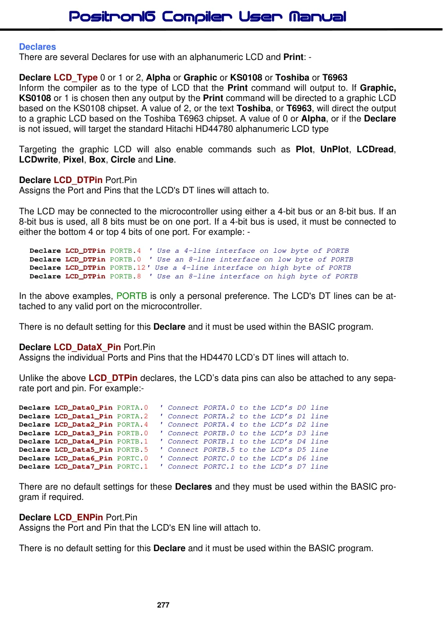
Text in this figure or table
Print $FE, 1 : DelayMs 102 lines x 16 characters Alphanumeric LCD
DB7 DB6 DB5 DB4 DB3 DB2 DB1 DB0 EN R/W RS Vo VddVss
To RB3 To RB2
+5 Volts To RB7To RB6To RB5To RB4
220Ω Contrast
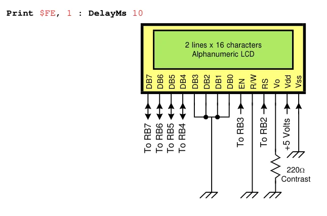
The above diagram shows typical connections for an alphanumeric LCD module using a 4-bit interface. Note that the compiler does not use the LCD's RW pin, and this must be connected to ground.